 Electronics
 Li-ion Battery Charging Protection Circuit Design: TP4056 and DW01 Practical Guide
Lithium batteries are the most common power solution for all embedded projects, but if not used properly, they can become “time bombs”. Overcharging causes swelling, over-discharging causes permanent damage, and short circuits cause smoking. Today we’re going to talk about how to design a reliable lithium battery charging protection circuit.
Why do we need protection circuits?
Lithium batteries are more temperamental than you think:
-
Overcharge (>4.2V): Lithium plating on positive electrode, internal pressure increases, may swell or even catch fire
-
Over-discharge (<2.5V): Copper current collector dissolves, battery permanently fails
-
Overcurrent/short circuit: Instantaneous high current, heating and fire
-
Over-temperature: High temperature accelerates aging, extreme cases lead to thermal runaway
An 18650 cell is nominally 3.7V, with an actual operating range of 3.0V~4.2V. Exceeding this range and the battery starts to “act up”.
Core chip: TP4056
TP4056 is currently the most popular linear lithium battery charging management IC, for a simple reason - cheap, easy to use, and requires few external components.
Key parameters
| Parameter | Value |
|---|---|
| Input voltage | 4.5V ~ 6.5V (USB 5V direct supply) |
| Charging current | Programmable, maximum 1A |
| Charging accuracy | ±1% (4.2V cutoff voltage) |
| Operating mode | Pre-charge → Constant Current (CC) → Constant Voltage (CV) |
| Package | SOP-8 / MSOP-10 |
| Unit price | About 0.3~0.8 yuan |
Three charging stages
TP4056’s charging process is divided into three stages:
-
Pre-charge stage: When battery voltage is below 3.0V, pre-charge with 10% of the set current to protect deeply discharged batteries
-
Constant Current Charging (CC): After pre-charge completes, charge with constant current (maximum 1A), battery voltage rises quickly to 4.2V
-
Constant Voltage Charging (CV): After voltage reaches 4.2V, maintain constant voltage, current gradually decreases, charging ends when current drops to 10% of the set value
Complete circuit design
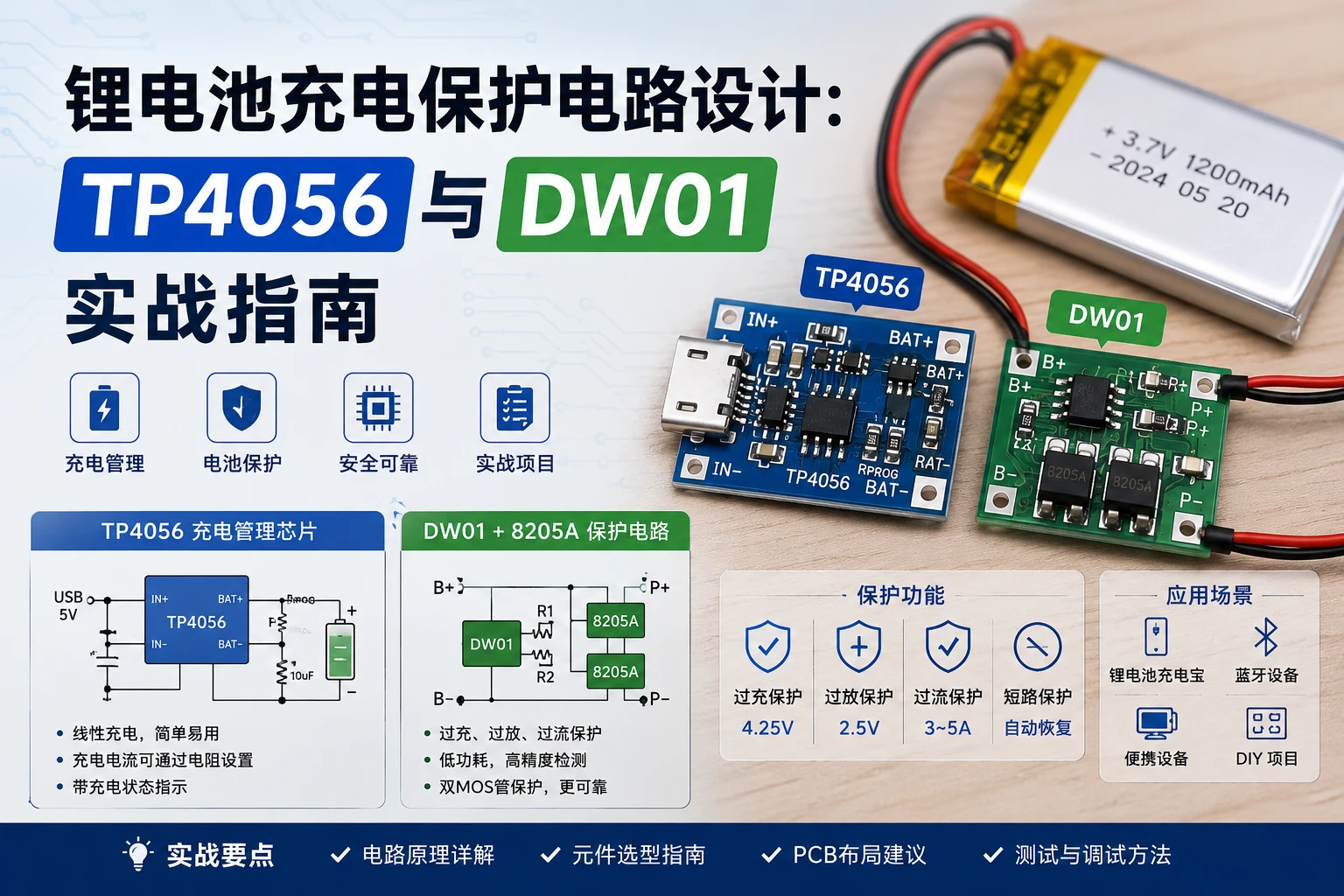
Solution 1: TP4056 module (recommended for beginners)
If you don’t want to design your own PCB, using a ready-made TP4056 module is the fastest solution:
Hardware list:
| Component | Model | Quantity | Unit price (yuan) |
|---|---|---|---|
| TP4056 charging module | With protection version (DW01+8205A) | 1 | 1.5 |
| 18650 lithium battery | Panasonic/NCR18650B | 1 | 15 |
| Micro-USB connector | Through-hole type | 1 | 0.2 |
| 1N5819 Schottky diode | Reverse charge protection | 1 | 0.1 |
Wiring method:
-
Micro-USB5V →TP4056 module IN+ -
TP4056 module B+→ Battery positive -
TP4056 module B-→ Battery negative -
TP4056 module OUT+/OUT-→ Load power output
Note: TP4056’s OUT and B are connected together, load and battery are in parallel. When charging while load is working simultaneously, charging current will be divided by the load, this is normal.
Solution 2: Discrete component design (advanced)
If you want to design your own PCB, here’s the complete principle:
VCC (5V USB)
            │
         ┌──┴──┐
         │ TP4056 │
         └──┬──┘
            │ BAT (4.2V)
         ┌──┴──┐
         │  Cell  │
         └──┬──┘
            │
      ┌─────┴─────┐
      │  DW01 + 8205A │ ← Protection IC
      └─────┬─────┘
            │
         PACK- (Output negative)
Core component list:
| Component | Model | Quantity | Unit price (yuan) | Function |
|---|---|---|---|---|
| Charging IC | TP4056 | 1 | 0.5 | Charging management |
| Protection IC | DW01-A | 1 | 0.15 | Overcharge/over-discharge detection |
| MOSFET | 8205A (dual N-MOS) | 1 | 0.1 | Charge/discharge control switch |
| Charging current setting resistor | 1.2kΩ | 1 | 0.01 | Set 1A charging current |
| Input capacitor | 10μF/10V | 1 | 0.05 | Input filtering |
| Output capacitor | 10μF/10V | 1 | 0.05 | Output filtering |
| Status LED | Red/green 0603 | 1 each | 0.02 | Charging status indication |
| Schottky diode | 1N5819 | 1 | 0.1 | Prevent battery reverse charge |
Charging current calculation formula:
I_CHARGE = 1000 / R_PROGRAM  (Unit: mA)

Example: R_PROGRAM = 1.2kΩ → I_CHARGE ≈ 833mA
         R_PROGRAM = 2kΩ   → I_CHARGE ≈ 500mA
         R_PROGRAM = 1.5kΩ → I_CHARGE ≈ 667mA
Choose charging current based on battery capacity, generally recommend 0.5C1C (C is battery capacity). 18650 commonly 20003400mAh, using 1A charging is appropriate.
DW01 protection circuit detailed explanation
DW01 is a single-cell lithium battery protection IC, with built-in overcharge comparator, over-discharge comparator and short circuit detection. Combined with 8205A (dual N-MOS) to achieve charge/discharge on/off control.
Protection thresholds
| Protection type | Trigger condition | Recovery condition |
|---|---|---|
| Overcharge protection | Battery voltage ≥ 4.25V ± 0.05V | Charging voltage drops to 4.15V ± 0.05V |
| Over-discharge protection | Battery voltage ≤ 2.4V ± 0.08V | Charging voltage rises to 3.0V ± 0.1V |
| Overcurrent protection | Discharge current too large (MOS Rds voltage drop exceeds standard) | Automatic recovery after load removed |
| Short circuit protection | Output terminal directly shorted | Automatic recovery after short circuit removed |
DW01 pin description
| Pin | Name | Function |
|---|---|---|
| 1 | CO | Overcharge control output → 8205A’s charging MOS |
| 2 | VM | Overcurrent/short circuit detection → in series in discharge loop |
| 3 | DO | Over-discharge control output → 8205A’s discharge MOS |
| 4 | VSS | Ground |
| 5 | CS | Battery positive detection input |
| 6 | VD | Internal oscillator (float or connect capacitor) |
Practical: Monitor battery status with Arduino
Protection circuits are the hardware level’s “last line of defense”, but we can also monitor battery status in real-time at the software level.
// Lithium battery voltage monitoring - Universal for Arduino/ESP32
// Read battery voltage through resistor voltage divider

const int BATTERY_PIN = A0;  // ADC input pin
const float R1 = 100000.0;   // Upper voltage divider resistor 100kΩ
const float R2 = 10000.0;    // Lower voltage divider resistor 10kΩ
const float ADC_REF = 3.3;   // ADC reference voltage (ESP32=3.3, Arduino=5.0)

float readBatteryVoltage() {
  int adcValue = analogRead(BATTERY_PIN);
  float voltage = (adcValue / 4095.0) * ADC_REF;  // ESP32 12-bit ADC
  // Restore voltage before voltage divider
  float batteryVoltage = voltage * (R1 + R2) / R2;
  return batteryVoltage;
}

float getBatteryPercent(float voltage) {
  // Simplified lithium battery discharge curve mapping
  if (voltage >= 4.20) return 100.0;
  if (voltage >= 4.10) return 95.0;
  if (voltage >= 4.00) return 85.0;
  if (voltage >= 3.90) return 70.0;
  if (voltage >= 3.80) return 55.0;
  if (voltage >= 3.70) return 40.0;
  if (voltage >= 3.60) return 25.0;
  if (voltage >= 3.50) return 15.0;
  if (voltage >= 3.40) return 8.0;
  if (voltage >= 3.30) return 4.0;
  if (voltage >= 3.00) return 1.0;
  return 0.0;  // Over-discharge protection triggered
}

void setup() {
  Serial.begin(115200);
  Serial.println("Lithium battery monitor started");
}

void loop() {
  float voltage = readBatteryVoltage();
  float percent = getBatteryPercent(voltage);

  Serial.printf("Voltage: %.2fV | Battery: %.0f%%\n", voltage, percent);

  if (voltage < 3.3) {
    Serial.println("⚠️  Warning: Low battery!");
  }

  if (voltage > 4.25) {
    Serial.println("⚠️  Warning: Overcharge! Check charging circuit");
  }

  delay(5000);
}
Voltage divider resistor selection key points:
The voltage after the divider must be ≤ ADC reference voltage. Taking 4.2V fully charged as an example:
V_ADC = 4.2 × R2 / (R1 + R2)

R1=100k, R2=10k → V_ADC = 4.2 × 10/110 ≈ 0.38V (safe)
R1=300k, R2=100k → V_ADC = 4.2 × 100/400 = 1.05V (safe)
Resistance values should not be too small, otherwise static power consumption is high. Recommend total resistance ≥ 100kΩ.
Common problem troubleshooting
1. Charging doesn’t complete (stops at 3.8V)
Cause:
-
Charging current set too large, battery internal resistance voltage drop causes CV stage to be reached early
-
Battery aged, internal resistance increased
-
USB power supply insufficient (computer USB port may only have 500mA)
Solution:
-
Check if R_PROGRAM resistance value is correct
-
Test with 2A charging adapter
-
Try replacing battery to rule out aging issues
2. Voltage drops rapidly after charging
Cause:
-
Battery internal resistance too large (aged or low-quality cells)
-
Charging disconnected before completion (CV stage requires longer time)
-
Load current too large
Solution:
-
TP4056’s CV stage may take 2~3 hours, be patient
-
Check if charging indicator light changed from red to green
-
Consider using battery with larger capacity
3. Protection board doesn’t discharge
Cause:
-
After over-discharge protection triggers, needs charging to recover
-
Load short circuit caused protection lockout
-
DW01’s CO/DO pin status abnormal
Solution:
-
Connect charger, charge above 3.0V to automatically recover
-
Remove load and reconnect
-
Use multimeter to check DW01 pin voltages
4. Charging chip overheating
Cause:
-
TP4056 is a linear charging chip, heating is normal when voltage difference is large
-
Input voltage too high (exceeds 6V)
-
Poor heat dissipation
Solution:
-
Ensure input voltage is 5V (USB standard)
-
Add thermal pad on bottom during PCB design (GND pad)
-
Consider adding small heatsink when charging with high current (>500mA)
-
If input voltage is high, switch to switching charging chip (such as CN3063)
5. Battery swelling
Cause:
-
Overcharge (protection circuit failed)
-
Charging current too large
-
Battery quality issues
Solution:
-
Immediately stop using swollen battery, safety risk exists
-
Check if protection circuit is working normally
-
Use branded cells (Panasonic, Samsung, LG)
-
Don’t mix new and old batteries
Design recommendations summary
-
Calculate charging current based on battery capacity, R_PROGRAM resistor accuracy recommend selecting ±1%
-
Must add DW01 + 8205A protection circuit, cannot rely solely on TP4056 for charging
-
Input/output capacitors cannot be omitted, 10μF tantalum capacitor or X5R ceramic capacitor both work
-
Use ADC to monitor battery voltage in real-time, software level provides dual protection
-
Choose branded cells (Panasonic, Samsung, LG), avoid using salvaged or low-quality batteries
Hardware list summary
| Component | Model | Quantity | Total price (yuan) |
|---|---|---|---|
| TP4056 charging IC | SOP-8 | 1 | 0.5 |
| DW01 protection IC | SOT-23-6 | 1 | 0.15 |
| 8205A MOSFET | SOT-26 | 1 | 0.1 |
| 18650 battery holder | Spring type | 1 | 0.3 |
| Resistors and capacitors | 0603 package | Several | 0.5 |
| Micro-USB connector | Through-hole | 1 | 0.2 |
| 18650 lithium battery | 2600mAh branded cell | 1 | 12 |
| Total | About 14 yuan |
Hope this blog post is helpful to you!