 Embedded Development
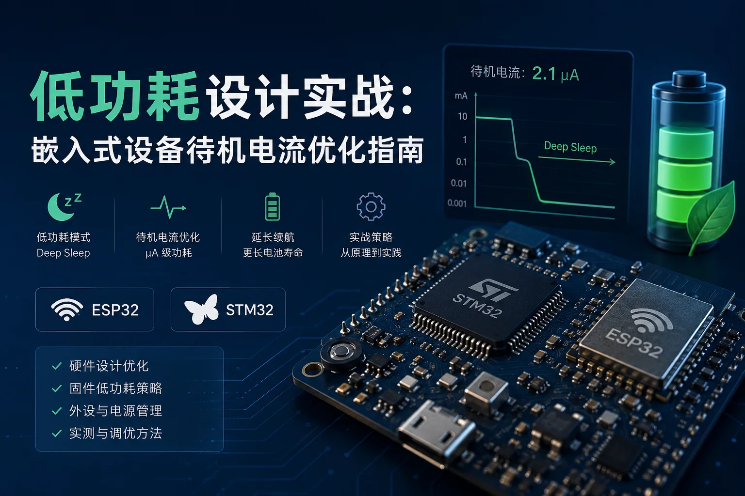
 Low Power Design in Practice: Embedded Device Standby Current Optimization Guide
When making battery-powered IoT devices, the biggest headache isn’t how to write the code, but how long the battery will last.
I made a soil moisture monitoring node with ESP32. At first, it ran out of power after 3 days of standby. Later, I spent a week optimizing power consumption and extended the standby time to 6 months. Today I’ll explain the pitfalls I encountered and the techniques I learned all at once.
Why is standby current so important?
Let’s do some math first. Suppose you use a 2000mAh lithium battery:
-
Standby 10mA → 200 hours, about 8 days
-
Standby 1mA → 2000 hours, about 83 days
-
Standby 100μA → 20000 hours, about 2.3 years
That’s a 250x difference.
Most IoT devices are in standby 99% of the time, only waking up occasionally to collect data or send messages. So standby power consumption directly determines battery life.
Hardware-level optimization
1. Choose the right chip
Not all MCUs are suitable for battery power. Look at the typical standby current of mainstream chips:
| Chip | Deep Sleep current | Wake-up time |
|---|---|---|
| ESP32-C3 | ~7μA (Hibernation) | ~20ms |
| STM32L053 | ~0.6μA (Stop mode) | ~5μs |
| nRF52840 | ~1μA (System OFF) | ~6μs |
| ATmega328P | ~0.1μA (Power Down) | ~65ms |
If battery life is the top priority, STM32L series and nRF series are better choices. ESP32’s advantage lies in integrated Wi-Fi/Bluetooth, but the cost is relatively higher power consumption.
2. Remove unnecessary loads
Many development boards have things you don’t need at all continuously consuming power:
-
Status LEDs: Each one 2-5mA, turning them off saves a lot
-
USB to serial chip: CH340 static current about 5-10mA
-
LDO voltage regulator: Old LDOs may have quiescent current as high as 1-5mA
Practical tip: Replace the onboard regulator with a low quiescent current LDO (such as MCP1702, Iq only 2μA), or directly power from lithium battery (3.0-4.2V range, many MCUs support it).
3. Floating pin handling
Unused GPIOs in floating state may cause internal circuits to toggle repeatedly, increasing μA-level leakage.
Solution: Configure all unused pins as output low, or internal pull-down.
Software-level optimization
ESP32’s four low power modes
ESP32 provides rich power consumption modes, from low to high:
| Mode | Typical current | Retained content | Wake-up method |
|---|---|---|---|
| Active (Wi-Fi) | 80-240mA | All | - |
| Modem Sleep | ~20mA | Wi-Fi connection | Automatic |
| Light Sleep | ~0.8mA | RTC memory | GPIO/Timer |
| Deep Sleep | ~10μA | RTC memory | Timer/GPIO/Touch |
| Hibernation | ~7μA | None | Timer |
Light Sleep in practice
Light Sleep is suitable for scenarios requiring frequent wake-ups, such as sampling sensors once per second:
#include "esp_sleep.h"
#include "esp_pm.h"

void setup() {
    // Configure Light Sleep auto-trigger
    // Automatically enter when CPU is idle
    esp_pm_config_esp32_t pm_config = {
        .max_freq_mhz = 80,
        .min_freq_mhz = 80,
        .light_sleep_enable = true
    };
    esp_pm_configure(&pm_config);
}

void loop() {
    // Read sensor
    float temp = read_sensor();

    // Send data
    send_data(temp);

    // Wait 1 second before collecting again
    // CPU automatically enters Light Sleep during idle period
    vTaskDelay(pdMS_TO_TICKS(1000));
}
Deep Sleep in practice
Deep Sleep is suitable for intermittent collection scenarios, such as sending data every 30 minutes:
#include "esp_sleep.h"

#define uS_TO_S 1000000ULL
#define SLEEP_TIME 1800  // 30 minutes

void setup() {
    // Configure timer wake-up
    esp_sleep_enable_timer_wakeup(SLEEP_TIME * uS_TO_S);

    // Optional: GPIO wake-up (such as pressing button to wake)
    // esp_sleep_enable_ext0_wakeup(GPIO_NUM_35, 1);

    // Optional: Save data to RTC Fast Memory
    RTC_DATA_ATTR uint32_t boot_count = 0;
    boot_count++;

    // Enter Deep Sleep
    esp_deep_sleep_start();
}

void loop() {
    // Never reaches here
    // After Deep Sleep wake-up, restarts from setup()
}
STM32’s Stop mode
STM32L series can achieve current as low as 0.6μA in Stop mode:
#include "stm32l0xx_hal.h"

void enter_stop_mode(void) {
    // Disable unnecessary clocks
    __HAL_RCC_GPIOA_CLK_DISABLE();
    __HAL_RCC_GPIOB_CLK_DISABLE();
    // ... disable all unused GPIO clocks

    // Enter Stop mode
    HAL_PWR_EnterSTOPMode(PWR_LOWPOWERREGULATOR_ON,
                          PWR_STOPENTRY_WFI);

    // Reconfigure clock after wake-up
    SystemClock_Config();
}
Power consumption measurement methods
You can’t optimize what you don’t measure. You need an accurate method to measure standby current.
Method 1: Multimeter (beginner)
Connect multimeter in series with power supply loop, read directly. Simple but limited accuracy, multimeter’s sampling rate is too low to see current spikes.
Method 2: Oscilloscope + sense resistor (recommended)
Connect a 10Ω sense resistor in series with the power supply loop, use oscilloscope to measure voltage across the resistor:
I = V / R = V(sense resistor) / 10ΩOscilloscope’s sampling rate is high, can see current spikes during wake-up - these spikes often account for a large portion of total power consumption.
Method 3: Dedicated power analyzer (professional)
Devices like Nordic Power Profiler Kit II or Joulescope can measure accurately to nA level, and can draw power consumption curves in real-time. If budget allows, highly recommended.
Common pitfalls and solutions
Pitfall 1: Forgot to disconnect Wi-Fi after connection
// Wrong - Wi-Fi stays connected all the time
WiFi.begin(ssid, password);
send_data();
delay(30000);  // Wi-Fi keeps consuming power during these 30 seconds!

// Correct - disconnect after use
WiFi.begin(ssid, password);
while (WiFi.status() != WL_CONNECTED);
send_data();
WiFi.disconnect(true);  // Disconnect Wi-Fi
WiFi.mode(WIFI_OFF);    // Turn off Wi-Fi module
esp_deep_sleep_start();
Pitfall 2: Sensor standby power consumption ignored
Many sensors have static current even when not working. For example, DHT22 has about 1.5mA in standby, which may be the biggest power consumer for the entire system.
Solution: Use GPIO to control sensor power supply, only power on when needed:
#define SENSOR_POWER_PIN 4

void setup() {
    pinMode(SENSOR_POWER_PIN, OUTPUT);
    digitalWrite(SENSOR_POWER_PIN, HIGH);  // Power on sensor
    delay(500);  // Wait for sensor to stabilize

    float temp = read_dht22();

    digitalWrite(SENSOR_POWER_PIN, LOW);   // Turn off sensor power
}
Pitfall 3: RTC GPIO wake-up configuration error
ESP32’s Deep Sleep can use GPIO to wake up, but pins are limited - can only use RTC GPIO (GPIO 0/2/4/12-15/25-27/32-39), and need to configure ULP coprocessor or ext0/ext1 wake-up sources.
// ext0 wake-up: can only use one pin, level triggered
esp_sleep_enable_ext0_wakeup(GPIO_NUM_35, 1);  // High level wake-up

// ext1 wake-up: can use multiple pins, supports OR/AND logic
esp_sleep_enable_ext1_wakeup(
    GPIO_SEL_35 | GPIO_SEL_34,  // Two pins
    ESP_EXT1_WAKEUP_ALL_LOW      // All low level triggered
);
Pitfall 4: ADC calibration causes abnormal current
If ULP coprocessor is enabled to read ADC during ESP32’s Deep Sleep, need to ensure correct configuration, otherwise may cause abnormal current after wake-up.
// Enable ADC calibration
esp_adc_cal_characteristics_t adc_chars;
esp_adc_cal_characterize(ADC_UNIT_1, ADC_ATTEN_DB_11,
                          ADC_WIDTH_BIT_12, 1100, &adc_chars);
Optimization results comparison
This is my actual optimization process for a soil monitoring node:
| Stage | Standby current | Battery life |
|---|---|---|
| Initial state (development board + Wi-Fi always on) | 15mA | 5.5 days |
| Remove LEDs + use independent power | 8mA | 10 days |
| Enable Light Sleep | 1.2mA | 69 days |
| Switch to Deep Sleep + timed collection | 15μA | 15 months |
| Remove onboard regulator + direct lithium battery | 8μA | 28 months |
From 5 days to 28 months, optimized 170x. The core idea is: turn off everything you can, sleep when you should sleep.
Summary
Low power design is not achieved overnight, but a continuous optimization process. Remember a few core principles:
-
Measure first, then optimize - use oscilloscope or power analyzer to quantify each module’s current consumption
-
Prioritize using Deep Sleep mode, turn off all peripherals you can, sleep when you should
-
Use GPIO to control sensor power supply, completely cut power when not in use, don’t let it standby
-
Choose the right chip and LDO - devices with low quiescent current can reduce standby current by an order of magnitude
-
Use RTC GPIO wake-up and ULP coprocessor to complete periodic tasks at extremely low power
Hope this blog post is helpful to you!