 Electronics
 2026 RS232 Pinout and Standard DB9 Interface Usage Explained
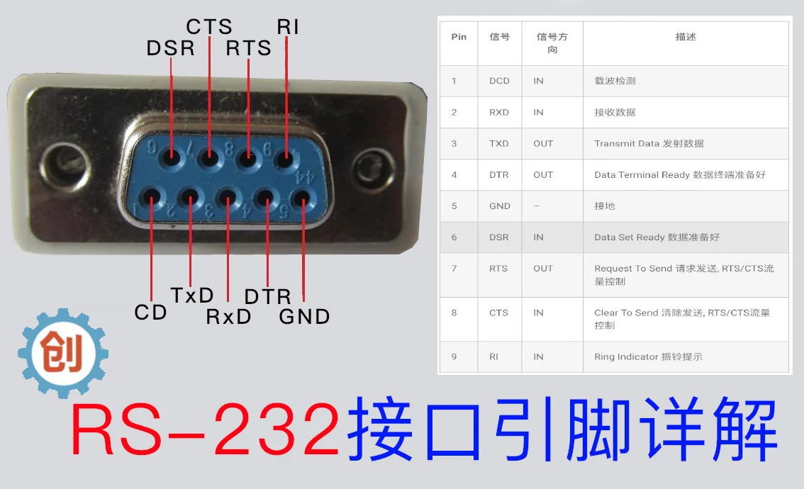
Below is the typical 9-pin RS232 pinout, this connector type is also known as the DB-9 connector.
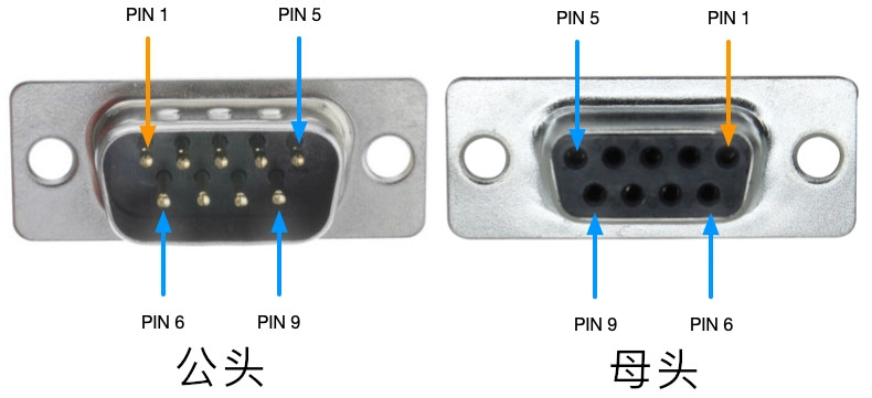
The computer’s COM port (DTE) is usually a male connector, and any peripheral device connected to this port usually has a female connector (DCE).
| Pin | Signal | Signal Direction | Description |
|---|---|---|---|
| 1 | DCD | IN | Data Carrier Detect |
| 2 | RXD | IN | Receive Data |
| 3 | TXD | OUT | Transmit Data |
| 4 | DTR | OUT | Data Terminal Ready |
| 5 | GND | - | Ground |
| 6 | DSR | IN | Data Set Ready |
| 7 | RTS | OUT | Request To Send, RTS/CTS flow control |
| 8 | CTS | IN | Clear To Send, RTS/CTS flow control |
| 9 | RI | IN | Ring Indicator |
What is RS232
RS232 is one of the telecommunications standard protocols used for serial communication of data. It is basically a protocol for connecting signals between data terminal equipment (DTE) such as file servers, routers, and application servers (such as modems).
The standard defines the electrical characteristics of signals, important timing, and specific physical dimensions of connectors. The RS232 standard is mainly used for computer ports. It involves two types of communication, serial and parallel.
Electrical Characteristics of RS232
Electrical characteristics refer to specifications based on voltage levels, signal change rates, and line resistance.
Voltage Levels
RS232 is called TTL logic, so RS232 uses TTL-specific 5V and GND logic levels. In this logic, “1” ranges from -15 volts to -3 volts, while logic “0” ranges from +3 volts to +15 volts, which means logic “1” is low voltage and logic “0” is high voltage. Usually logic “0” is about +12 volts and logic “1” is about -12 volts. Voltage is relative to “GND”, a common ground pin. Voltages between -3V and +3V are called undefined logic states. Logic “1” is also called mark, and logic “0” is called space.
Slew Rate
One of the most important characteristics is the rate of signal level change, called the slew rate. In RS232, the maximum slew rate is always maintained at 30V/µs. Due to these limitations of the standard, it helps reduce crosstalk with other signals. The maximum transmission rate of RS232 is 20kbps.
Communication
The RS-232 standard only allows one-to-one communication, supports bidirectional transmission, full duplex.
Line Impedance
Line impedance is the resistance between DTE and DCE lines, approximately 3Ω to 7Ω. According to the RS232 standard, there are two different cable lengths. The earlier RS232 standard defined the maximum cable length as 15 meters, while the revised standard specifies that the maximum length is determined by the capacitance per unit length of the cable.
Working Principle
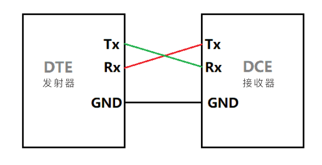
In RS232 standard devices, one wire transmits varying voltage and the other wire is grounded because the wire has a single-ended configuration. Noise caused by the ground voltage difference between driver and receiver circuits can affect single-ended signals. Information or data in the RS232 standard is transmitted serially in one direction through only one data line. To achieve bidirectional communication, three wires (RX, TX, and GND) plus control signals are required. One byte of information can be transmitted at any time because the data from the previous byte has already been transmitted.
RS232 strictly follows the asynchronous communication protocol, which means there is no clock signal to synchronize the sender and receiver. Therefore, it requires start bits and stop bits to notify the receiver when to check the data. There is a certain time delay between the transmission of each bit. This delay is the inactive state, meaning the signal is set to -12 volts or logic “1”, as mentioned earlier, logic 1 is -12 volts and logic 0 is 12 volts in RS232.
First, the transmitter (i.e., DTE) sends a start bit to the receiver (i.e., DCE), notifying it that data transmission starts from the next bit. We always keep the start bit as logic 0 or +12 volts, and the next 5 to 9 characters are data bits.
If a parity bit is used, up to 8 bits can be transmitted, and if no parity bit is used, 9 data bits can be transmitted. After successfully sending the data, the transmitter sends a stop bit, which can be 1 bit, 2 bits, or 5 bits long.
Since RS232 is a complete standard, many manufacturers do not follow the standard. Some comply with the complete identification, while others only partially follow the specification.
This is because of this variation in RS232 standard implementation, not all devices and applications require the full specification and functionality of the RS232 protocol. For example, a serial model using RS2323 may require more control lines than a serial mouse using a serial port.
Limitations
-
To operate RS232, a common ground is required between transmitter and receiver. This is why short cables are used between DTE and DCE in the RS232 protocol.
-
If the baud rate increases as cable length increases, it is very likely that crosstalk will be suppressed by the capacitance between cables.
-
Signals in the line are extremely susceptible to noise, which can be internal or external.
-
RS232 voltage levels are not compatible with modern TTL systems. For this reason, an external level converter is required.