 Electronics
 USB Pinout and Color Code Reference: Complete Type-A/B/C Analysis (2026)
USB Introduction and Pinout
USB, short for Universal Serial Bus, has become the standard interface for connecting computers and peripherals since its introduction in 1996. Over time, USB has undergone multiple iterations, bringing higher data transfer speeds and greater power delivery capabilities.
USB Versions and Speeds
The following are the main USB versions and their data transfer speeds:
-
USB 1.0/1.1: 1.5 Mbps or 12 Mbps
-
USB 2.0: 480 Mbps
-
USB 3.0 (USB 3.1 Gen 1): 5 Gbps
-
USB 3.1 (USB 3.1 Gen 2): 10 Gbps
-
USB 3.2: Up to 20 Gbps
-
USB4: Up to 40 Gbps (v1.0) / 80 Gbps (v2.0)
USB Connector Types
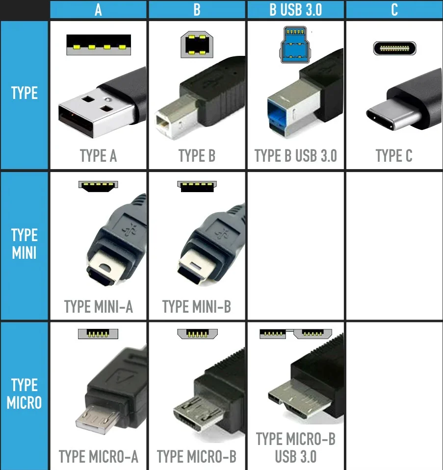
To meet the needs of different devices, USB has developed various connector types:**
-
Type-A**: The most common type, used to connect to host ports on computers
-
Type-B: Usually used to connect to peripherals such as printers and scanners
-
Mini-A, Mini-B and Micro-B: Smaller connectors designed for mobile devices
-
Type-C: A newer reversible connector used for data transfer and power delivery, mainly used for USB 3.1, USB 3.2 and USB4
USB Pinout
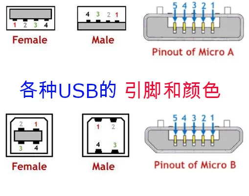
USB 1.x/2.0
| Pin | Name | Cable Color | Description |
|---|---|---|---|
| 1 | VBUS | Red | +5V Power |
| 2 | D− | White | Data Line – |
| 3 | D+ | Green | Data Line + |
| 4 | GND | Black | Ground |
USB 3.0
| Pin | Type-A Connector | Type-B Connector | Cable Color | Description |
|---|---|---|---|---|
| 1 | VBUS | Red | Red | Power |
| 2 | D- | D- | White | 2.0 Data Differential Pair – |
| 3 | D+ | D+ | Green | 2.0 Data Differential Pair + |
| 4 | GND | GND | Black | Power Ground |
| 5 | StdA_SSRX− | StdB_SSTX− | Blue | High-Speed Data Differential Pair – Receive |
| 6 | StdA_SSRX+ | StdB_SSTX+ | Yellow | High-Speed Data Differential Pair + Receive |
| 7 | GND_DRAIN | N/A | N/A | Signal Ground |
| 8 | StdA_SSTX− | StdB_SSRX− | Purple | High-Speed Data Differential Pair – Transmit |
| 9 | StdA_SSTX+ | StdB_SSRX+ | Orange | High-Speed Data Differential Pair + Transmit |
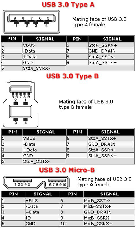
Type-A/Type-B Interface
| Pin | Name | Cable Color | Description |
|---|---|---|---|
| 1 | VBUS | Red or Orange | +5V Power |
| 2 | D- | White or Gold | Differential Data – |
| 3 | D+ | Green | Differential Data + |
| 4 | GND | Black or Blue | Ground |
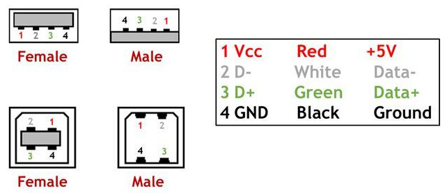
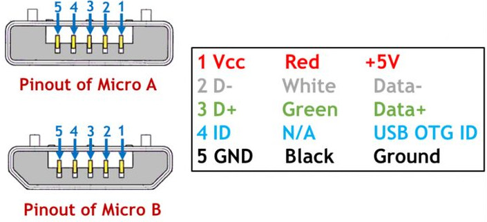
Mini/Micro-A/B Interface
-
Mini USB Pin 4 is ID, other pin functions are the same as standard USB.
-
ID Pin: Connected to Pin 5 (GND) on Mini-A, can be left floating or connected to Pin 5 on Mini-B.
| Pin | Name | Cable Color | Description |
|---|---|---|---|
| 1 | VBUS | Red | +5V Power |
| 2 | D- | White | Differential Data – |
| 3 | D+ | Green | Differential Data + |
| 4 | ID | N/A | Distinguishes other end interface type**A Interface (Host): Grounded |
| B Interface (Device): Not Connected | |||
| 5 | GND | Black | Ground |
Type-C Interface Pinout and Colors
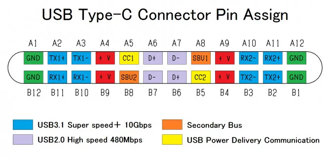
| Pin | Name | Wire Color | Description | USB 2.0 | USB 3.x |
|---|---|---|---|---|---|
| A1 | GND | Black | Ground | ✓ | ✓ |
| A2 | TX1+ | Yellow | SuperSpeed Differential Pair 1 Transmit+ | ✓ | |
| A3 | TX1- | Blue | SuperSpeed Differential Pair 1 Transmit- | ✓ | |
| A4 | VBUS | Red | +5V Power | ✓ | ✓ |
| A5 | CC1 | Configuration Channel 1 | ✓ | ||
| A6 | D+ | Green | USB 2.0 Differential Data+ | ✓ | |
| A7 | D- | White | USB 2.0 Differential Data- | ✓ | |
| A8 | SBU1 | Sideband Use | |||
| A9 | VCONN | Active Cable Power | |||
| A10 | RX1- | Purple | SuperSpeed Differential Pair 1 Receive- | ✓ | |
| A11 | RX1+ | Orange | SuperSpeed Differential Pair 1 Receive+ | ✓ | |
| A12 | GND | Black | Ground | ✓ | ✓ |
| B1 | GND | Black | Ground | ✓ | ✓ |
| B2 | TX2+ | SuperSpeed Differential Pair 2 Transmit+ | ✓ | ||
| B3 | TX2- | SuperSpeed Differential Pair 2 Transmit- | ✓ | ||
| B4 | VBUS | Red | +5V Power | ✓ | ✓ |
| B5 | CC2 | Configuration Channel 2 | ✓ | ||
| B6 | D+ | Green | USB 2.0 Differential Data+ | ✓ | |
| B7 | D- | White | USB 2.0 Differential Data- | ✓ | |
| B8 | SBU2 | Sideband Use | |||
| B9 | VBUS | Red | +5V Power | ✓ | ✓ |
| B10 | RX2- | SuperSpeed Differential Pair 2 Receive- | ✓ | ||
| B11 | RX2+ | SuperSpeed Differential Pair 2 Receive+ | ✓ | ||
| B12 | GND | Black | Ground | ✓ | ✓ |
Notes:**
-
The table lists the 24 pins of the Type-C interface, classified by function and module.
-
For the USB 2.0 module, the table lists the 4 pins it uses and their corresponding colors.
-
For the USB 3.x module, the table lists the 8 pins it uses and their corresponding colors. Note that not all Type-C interfaces support USB 3.x modules.
-
The table also lists some other pins, such as CC1, CC2, VCONN, etc., which are used for configuration and power functions.
-
Some pins do not have specific color assignments.
Additional Notes:
-
Type-C interface supports reversible plug, so the USB 2.0 module uses two sets of identical D+/D- pins.
-
Some Type-C cables contain chips internally to enhance signals or implement special functions, these cables are called active cables, and the VCONN pin is used to power them.
-
SBU1 and SBU2 pins can be used for sideband purposes, such as audio transmission, etc.
{ “@context”: “https://schema.org”, “@type”: “FAQPage”, “mainEntity”: [ { “@type”: “Question”, “name”: “What are the USB 3.0 wire color codes and definitions?”, “acceptedAnswer”: { “@type”: “Answer”, “text”: “USB 3.0 standard interface contains 9 pins: VCC (red/power), D- (white), D+ (green), GND (black) are USB 2.0 compatible pins, newly added StdA_SSRX-/+(blue), StdA_SSTX-/+(purple) and GND_DRAIN for SuperSpeed data transmission. The interface color is usually blue to distinguish from USB 2.0’s black interface.” } }, { “@type”: “Question”, “name”: “What is the difference between USB Type-A and Type-C pins?”, “acceptedAnswer”: { “@type”: “Answer”, “text”: “USB Type-A is the traditional USB interface (4-pin USB 2.0 / 9-pin USB 3.0), Type-C is the new generation reversible plug interface (24-pin), supporting higher power (100W+), USB 3.1/3.2/4 high-speed transmission and Alt Mode video output. Type-C pin definition is more complex, containing multiple sets of TX/RX differential pairs and configuration channels.” } }, { “@type”: “Question”, “name”: “What do USB interface colors represent?”, “acceptedAnswer”: { “@type”: “Answer”, “text”: “USB interface colors are used to identify versions: white/black = USB 1.x/2.0, blue = USB 3.0 (3.1 Gen 1), teal = USB 3.1 Gen 2, red/yellow = shutdown charging port (Always On). Type-C interfaces themselves have no color differentiation standard.” } }, { “@type”: “Question”, “name”: “How to determine if a USB cable supports fast charging?”, “acceptedAnswer”: { “@type”: “Answer”, “text”: “Fast charging USB cables need to support larger currents (3A or above), Type-C to Type-C cables have built-in E-Marker chips that can support 5A/100W (USB PD protocol). Regular USB-A cables only support up to 2.4A maximum. Can be identified by cable markings (such as 5A, 60W, 100W) or tested using a USB tester.” } } ] }