 Embedded Development
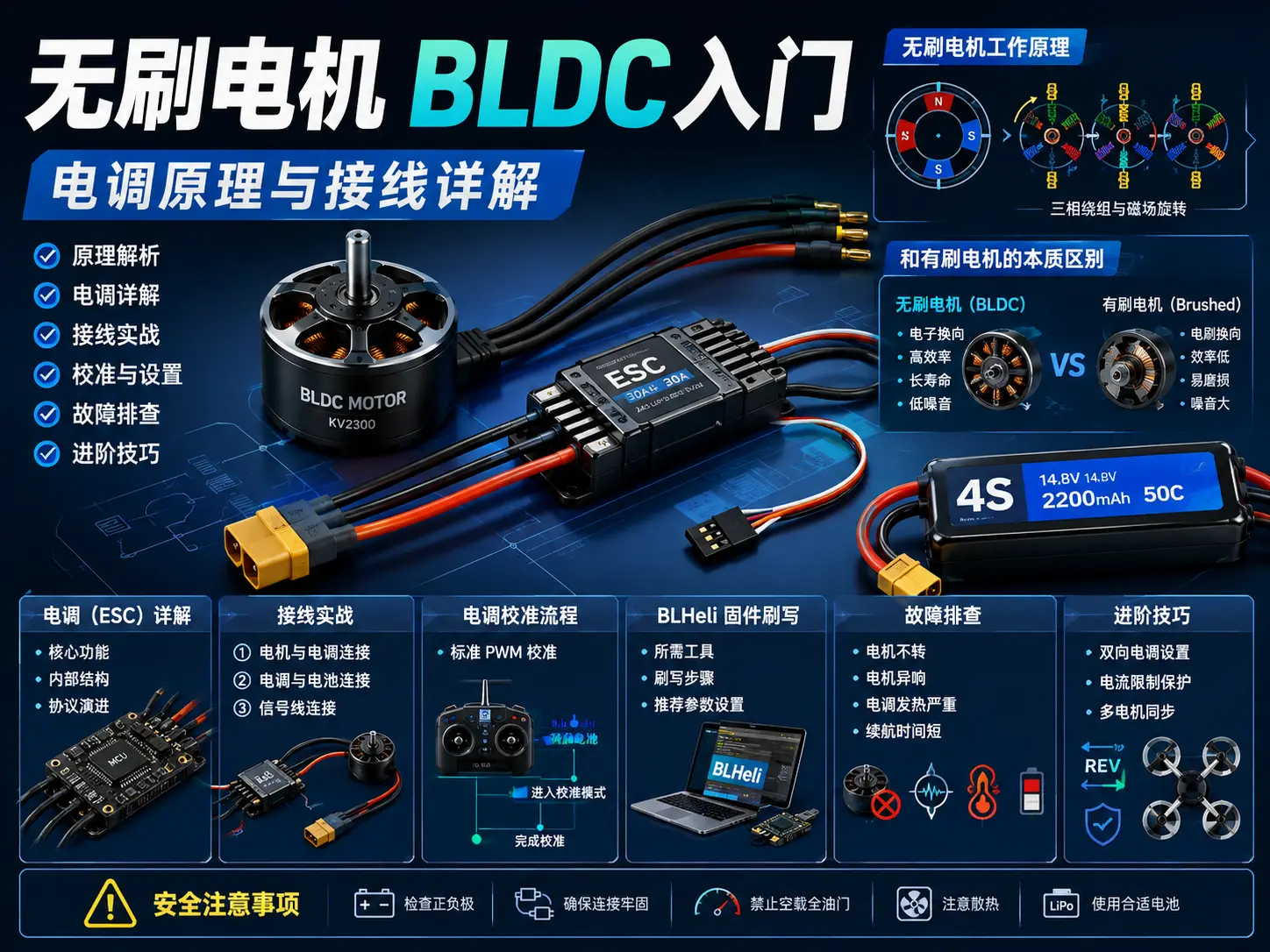
 Brushless Motor BLDC Introduction: ESC Principles and Wiring Explained in Detail
Why choose brushless motors?
If you’ve played with drones, RC cars, or power tools, you’ve definitely heard the term “brushless motor”. Compared to traditional brushed motors, brushless motors (BLDC - Brushless Direct Current) have longer lifespan, higher efficiency, and lower noise. But many people are confused when they first get one: how do you wire this thing? What is an ESC? How do you give it PWM signals?
Today we’re going to thoroughly understand brushless motors and ESCs.
Hardware list
| Component | Model | Price | Notes |
|---|---|---|---|
| Brushless motor | A2212 1000KV | ¥45 | Best for beginners, suitable for 1045 propellers |
| ESC | GoodSky 30A | ¥35 | Supports OneShot125 |
| LiPo battery | 3S 2200mAh | ¥65 | 11.1V standard voltage |
| Transmitter | FlySky FS-i6 | ¥280 | 6 channels enough for beginners |
| Receiver | FS-iA6B | ¥80 | With IBUS protocol |
| Power module | XT60 power distribution board | ¥15 | Multi-ESC power supply |
| Jumper wires | Male-to-female 20cm | ¥5 | Signal connection |
| Total | - | ¥525 | Beginner kit |
How brushless motors work
The essential difference from brushed motors
Brushed motors rely on carbon brushes and commutators for mechanical commutation. Over time, the carbon brushes wear out and need replacement. Brushless motors are the opposite: the coils are stationary on the stator, the magnets rotate on the rotor, and commutation is done electronically.
Simply put: mechanical commutation becomes electronic commutation.
Three-phase windings and rotating magnetic field
Inside a brushless motor there are three sets of coils (A/B/C three-phase). The ESC energizes these three phases in sequence, creating a rotating magnetic field that drives the rotor magnets to follow.
Energization sequence: A+ → B- → A- → C+ → B+ → C- → cycleThis sequence switches thousands of times per second, and the motor spins. The higher the KV value, the faster the RPM per volt of applied voltage.
ESC detailed explanation
Core functions of an ESC
ESC stands for Electronic Speed Controller. It does three things:
-
Converts DC to three-phase AC: The battery provides DC (Direct Current), but brushless motors need three-phase AC (Alternating Current) to drive them. The MOSFET bridge inside the ESC handles this conversion.
-
Adjusts speed based on control signals: By receiving PWM/DShot signals from the flight controller or receiver, the ESC precisely controls the switching frequency and duty cycle of the three-phase power, thus regulating motor speed.
-
Provides stable 5V power supply (BEC): Most ESCs have a built-in BEC (Battery Eliminator Circuit) that can step down the main battery voltage to output 5V, directly powering the flight controller and receiver, eliminating the need for an extra battery.
ESC internal structure
Open up a 30A ESC and you’ll see:
-
MCU: Usually an 8-bit microcontroller running the commutation algorithm
-
MOSFETs: 6 of them forming a three-phase bridge, 6 per ESC
-
BEC: 5V regulated output for powering flight controller/receiver
-
Capacitors: Filter and stabilize voltage, prevent voltage spikes
ESC protocol evolution
| Protocol | Refresh rate | Latency | Application scenario |
|---|---|---|---|
| PWM | 50-490Hz | High | Beginner practice |
| OneShot125 | 8kHz | Medium | Racing drones |
| OneShot42 | 24kHz | Low | Professional racing |
| DShot600 | 600kHz | Very low | Top-level racing |
| DShot1200 | 1200kHz | Lowest | F7 flight controllers |
Beginners should start with standard PWM first, then upgrade to OneShot or DShot once familiar.
Wiring in practice
Step 1: Motor to ESC connection
You can connect the three wires of a brushless motor in any order! Connecting them backwards will only reverse the direction, it won’t damage anything. If you find the rotation direction is wrong, just swap any two wires.
# ESC three wires → Motor three wires
ESC yellow wire → Motor any wire
ESC blue wire → Motor any wire
ESC green wire → Motor any wireNote: Use heat shrink tubing to cover solder joints to prevent short circuits.
Step 2: ESC to battery connection
The ESC’s two thick wires (red + black -) connect to the battery. A 3S LiPo battery is nominally 11.1V, fully charged 12.6V.
Battery XT60 male → ESC XT60 female
Red wire (+) → Red wire (+)
Black wire (-) → Black wire (-)Warning: Positive and negative must never be reversed! It will instantly burn out the ESC.
Step 3: Signal wire connection
The ESC’s signal wire (usually white or yellow) connects to the flight controller or receiver’s PWM output.
ESC signal wire → Flight controller MOTOR1 pad
ESC red wire (5V) → Flight controller 5V (if powering flight controller)
ESC black wire (GND) → Flight controller GND
For multi-ESC systems (like quadcopters), each ESC’s signal wire connects to the flight controller’s M1/M2/M3/M4 respectively.
ESC calibration process
New ESCs must be calibrated for throttle range first, otherwise they may not start or may have abnormal RPM.
Standard PWM ESC calibration
# Calibration steps (using GoodSky 30A as example)

1. Battery disconnected, ESC signal wire connected to receiver channel 1
2. Transmitter throttle pushed to maximum (100%)
3. Connect battery, ESC beeps "beep - beep" twice
4. Within 2 seconds, pull throttle to minimum (0%)
5. ESC beeps "beep - beep - beep" three times, calibration complete
6. Gently push throttle, motor should start smoothly
Common issues
Issue 1: ESC keeps beeping “beep beep beep” alarm
-
Cause: Throttle not at zero or calibration failed
-
Solution: Recalibrate, ensure throttle is at minimum position
Issue 2: Motor vibrates but doesn’t spin
-
Cause: Phase identification failed or load too heavy
-
Solution: Check wiring, remove propeller before testing
Issue 3: Only spins in one direction
-
Cause: ESC in unidirectional mode
-
Solution: Some ESCs support bidirectional, requires special settings
BLHeli firmware flashing
Factory ESC firmware has limited functionality, recommended to flash BLHeli firmware to unlock more features.
Required tools
-
BLHeliSuite software (Windows)
-
USB to TTL module (CP2102 or CH340)
-
ESC programming cable (3-pin jumper wires)
Flashing steps
# Flashing via BLHeliSuite

1. ESC GND/SIG/+5V connected to TTL module
2. TTL module USB connected to computer
3. Open BLHeliSuite, select interface
4. Click "Read Setup" to read current firmware
5. Select "Flash BLHeli" to flash new version
6. After flashing complete, click "Write Setup" to save configuration
Recommended parameter settings
Motor Direction: Normal
Motor Timing: Auto (or Medium)
Startup Power: 0.030 (gentle start)
Startup RPM: 400 (suitable for large propellers)
RPM Power Protection: Enabled
Demag Compensation: High
Troubleshooting guide
Motor doesn’t spin
| Symptom | Possible cause | Solution |
|---|---|---|
| No response at all | Battery dead/disconnected | Measure battery voltage |
| ESC alarm | Throttle not at zero | Recalibrate throttle |
| Motor vibrates | Phase error | Swap any two phase wires |
| Spins then stops | Overcurrent protection | Check if jammed/load too heavy |
Motor makes abnormal noise
High-frequency whining: PWM frequency issue, try adjusting Motor Timing
Clicking sound: Bearing damaged or magnet fallen off, replace motor
Humming sound: Low KV motor paired with high voltage, check KV value matching
ESC overheating
-
ESC amperage insufficient: Motor’s actual operating current exceeds ESC rating. A 30A ESC paired with large propellers or high KV motors can easily overload, recommend leaving 20%-30% margin.
-
Poor heat dissipation: ESC sealed inside fuselage, no airflow passing through. Ensure ESC has ventilation space around it, add heatsinks or use a small fan to blow directly if necessary.
-
Motor Timing set too high: Excessive timing causes commutation efficiency to drop and heat generation to increase. Use BLHeli to set timing back to Auto or Medium and try.
Short battery life
-
Check if propeller is matched (large propeller with low KV)
-
Battery aged with capacity degradation
-
ESC efficiency low (switch to one supporting OneShot)
Advanced techniques
Bidirectional ESC setup
Some applications (like robot chassis) need motor forward/reverse rotation. BLHeli supports bidirectional mode:
Bidirectional Mode: On
Deadband: 3μs
After setting, throttle midpoint stops, forward goes forward, backward goes reverse.
Current limit protection
Set current limit in BLHeli to prevent burnout:
Current Limit: 25A (slightly below ESC rating)
Thermal Throttling: Enabled
The ESC will automatically limit output current, protecting motor and battery.
Multi-motor synchronization
Quadcopter drones need four motors to synchronize strictly. Using DShot digital protocol can eliminate PWM jitter:
Protocol: DShot600
Telemetry: Enabled (requires flight controller support)
ESCs with telemetry can report back RPM, temperature, and current data.
Safety precautions
-
Always remove propellers when testing! This is the most important rule. When debugging ESC, flashing firmware, or calibrating throttle, the motor may start suddenly, propellers can cause serious cuts.
-
LiPo batteries must never be over-discharged or overcharged: A single LiPo cell below 3.3V will be permanently damaged, overcharging to 4.2V can cause fire or explosion. Use a dedicated balance charger, never leave charging unattended.
-
Check positive/negative before connecting: Reversing battery polarity will instantly burn out the ESC, and may even cause LiPo battery short circuit and fire. After wiring, visually confirm once before powering on.
-
Insulation protection when soldering: Connection points between ESC and motor, battery must be covered with heat shrink tubing or insulating tape, exposed solder joints may short circuit during vibration.
-
Test away from flammable materials: First power-on test should be done on an open desktop, away from paper, cloth and other flammable materials. Keep fire extinguishing sand or fire extinguisher nearby in case of LiPo fire.
Summary
Brushless motor systems may seem complex, but the core is just three points:
-
ESC is the soul: It’s responsible for converting battery DC to three-phase AC, and precisely adjusting speed based on control signals. Choosing the right ESC (current margin, protocol matching flight controller) is more important than choosing the motor.
-
Wiring is simple: Motor’s three wires can be connected in any order, if reversed just swap any two; signal wires correspond to flight controller markings; battery positive/negative must never be reversed.
-
Debugging requires patience: New ESCs must calibrate throttle range first, then flash BLHeli firmware to unlock advanced features, follow troubleshooting table step by step when encountering problems.
After mastering this basic knowledge, you can confidently play with drones, electric models, or DIY power tools. When encountering problems, follow the troubleshooting table in this article step by step, 90% of issues can be resolved.
Hope this blog post is helpful to you!