 IoT
IoT 2026 Industrial IoT Practice: ESP32 Modbus RTU to MQTT Protocol Bridge
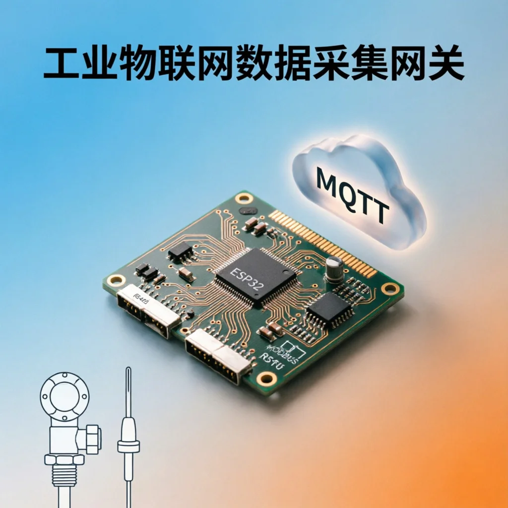
Industrial sites have massive amounts of legacy equipment still using Modbus RTU protocol communicating over RS485 buses. These devices have no networking capability themselves. But what if you want to push their data to the cloud for remote monitoring? The most practical solution is to build a protocol bridge gateway - read Modbus RTU data and convert it to MQTT to send to the cloud platform.
Today we’ll use an ESP32 plus an RS485 module to build an industrial data collector from scratch. No PLC needed, no expensive industrial gateway required, cost under 100 yuan.
Why Modbus RTU to MQTT is Needed
Modbus RTU is one of the most fundamental communication protocols in industry, supported by大量 sensors, instruments, and variable frequency drives. But it has a fatal flaw: it only runs on RS485 buses, limited transmission distance, and can’t directly access the internet.
MQTT is the opposite - lightweight, TCP/IP-based, naturally suited for the cloud. Bridging the two is like giving traditional industrial equipment “wings”.
This solution is particularly suitable for:
-
Factory workshop temperature/pressure/flow data remote collection
-
Building automation system (BAS) data to cloud
-
Agricultural greenhouse environmental sensor networking
-
Legacy equipment retrofit, no need to replace entire system
Hardware List
| Component | Model | Quantity | Reference Price |
|---|---|---|---|
| Main board | ESP32-WROOM-32 development board | 1 | ¥25 |
| RS485 module | MAX485 TTL to RS485 | 1 | ¥5 |
| Debug Modbus device | Temperature/humidity transmitter RS485 output | 1 | ¥35 |
| Connection cables | Jumper wires | 1 set | ¥3 |
| Power supply | 5V/1A adapter | 1 | ¥8 |
| Total | About ¥76 |
If you already have field equipment supporting Modbus RTU, you can skip the temperature/humidity transmitter.
Wiring Instructions
Wiring from ESP32 to MAX485 module is straightforward:
| MAX485 Pin | ESP32 Pin | Description |
|---|---|---|
| DI | GPIO17 (TX) | Data input |
| RO | GPIO16 (RX) | Data output |
| DE + RE | GPIO4 | Transmit/receive control |
| VCC | 5V | Power |
| GND | GND | Ground |
RS485 bus wiring:
-
A+ connects to all devices’ A terminal (positive)
-
B- connects to all devices’ B terminal (negative)
-
Both ends of bus need 120Ω termination resistors (required when cable length exceeds 100 meters)
⚠️ Notes:
-
All devices must share common ground, otherwise communication is unstable
-
RS485 is differential signal, A/B cannot be reversed, reversal will cause complete data read failure
-
DE and RE shorted together then connected to same GPIO, high level for transmit, low level for receive
Software Implementation
We use Arduino IDE + two key libraries:
-
ModbusMaster— Modbus RTU master protocol stack -
PubSubClient— MQTT client
Install libraries first, search and install in Arduino IDE.
Complete Code
#include <ModbusMaster.h>
#include <WiFi.h>
#include <PubSubClient.h>

// WiFi configuration
const char* ssid = "YourWiFi";
const char* password = "YourPassword";

// MQTT configuration
const char* mqtt_server = "broker.emqx.io";
const int mqtt_port = 1883;
const char* mqtt_client_id = "modbus-gateway-001";
const char* mqtt_topic = "factory/sensor/data";

// RS485 pins
#define RX_PIN    16
#define TX_PIN    17
#define DE_RE_PIN 4

ModbusMaster node;
WiFiClient espClient;
PubSubClient mqtt(espClient);

// Control RS485 transmit/receive
void preTransmission() {
    digitalWrite(DE_RE_PIN, HIGH);
}

void postTransmission() {
    digitalWrite(DE_RE_PIN, LOW);
}

void setup() {
    Serial.begin(115200);

    // Initialize RS485 control pin
    pinMode(DE_RE_PIN, OUTPUT);
    digitalWrite(DE_RE_PIN, LOW);

    // Initialize Modbus master
    node.begin(1, Serial2);  // Slave address 1
    node.preTransmission(preTransmission);
    node.postTransmission(postTransmission);

    // Configure Serial2 RX/TX
    Serial2.begin(9600, SERIAL_8N1, RX_PIN, TX_PIN);

    // Connect WiFi
    WiFi.begin(ssid, password);
    Serial.print("Connecting WiFi");
    while (WiFi.status() != WL_CONNECTED) {
        delay(500);
        Serial.print(".");
    }
    Serial.println("\nWiFi connected: " + WiFi.localIP().toString());

    // Connect MQTT
    mqtt.setServer(mqtt_server, mqtt_port);
    mqtt_connect();
}

void mqtt_connect() {
    while (!mqtt.connected()) {
        if (mqtt.connect(mqtt_client_id)) {
            Serial.println("MQTT connected");
        } else {
            Serial.print("MQTT connect failed: ");
            Serial.println(mqtt.state());
            delay(3000);
        }
    }
}

void loop() {
    if (!mqtt.connected()) {
        mqtt_connect();
    }
    mqtt.loop();

    // Read Modbus registers (holding registers starting from 0x0000, read 2 registers)
    uint8_t result = node.readHoldingRegisters(0x0000, 2);

    if (result == node.ku8MBSuccess) {
        // Assume register 0 = temperature(×10), register 1 = humidity(×10)
        float temperature = node.getResponseBuffer(0x00) / 10.0;
        float humidity = node.getResponseBuffer(0x01) / 10.0;

        // Build JSON message
        String payload = "{";
        payload += "\"temperature\":" + String(temperature, 1) + ",";
        payload += "\"humidity\":" + String(humidity, 1) + ",";
        payload += "\"timestamp\":" + String(millis());
        payload += "}";

        // Publish to MQTT
        if (mqtt.publish(mqtt_topic, payload.c_str())) {
            Serial.println("Published: " + payload);
        }
    } else {
        Serial.print("Modbus error: ");
        Serial.println(result, HEX);
    }

    delay(5000);  // Collect once every 5 seconds
}
Code Key Points
-
RS485 transmit/receive control via DE_RE_PIN, pull high before transmit, pull low after transmit, ModbusMaster library callbacks handle automatically
-
Read holding registers using
readHoldingRegisters()method, pass starting address and register count -
Convert register raw values to actual physical quantities (like divide by 10 to get temperature), then package as JSON and publish to MQTT
MQTT Message Format
Collector publishes a JSON message to factory/sensor/data every 5 seconds:
{
  "temperature": 23.5,
  "humidity": 65.2,
  "timestamp": 123456789
}
In the cloud you can use Node-RED, InfluxDB + Grafana, or even directly subscribe to this topic with Home Assistant for data visualization and alerts.
Common Problem Troubleshooting
Problem 1: Modbus Read Returns Error Code
This is the most common pitfall. Error code reference table:
| Error Code | Meaning | Troubleshooting Direction |
|---|---|---|
| 0xE2 | Invalid response | Check baud rate, slave address are correct |
| 0xE4 | Timeout | Check if A/B wires reversed, termination resistors in place |
| 0xE6 | Data checksum failed | Check serial parameters (8N1), cable quality |
Troubleshooting steps:
-
Verify slave device manual, confirm baud rate (commonly 9600), data bits (8), stop bits (1), parity (none) settings are correct
-
Check if slave address matches parameter in code
node.begin(), default is 1 -
Use multimeter to measure RS485 bus A-B voltage, should fluctuate between 0.2V~5V during normal communication, and confirm termination resistors (120Ω) are installed
Problem 2: MQTT Connection Repeatedly Disconnects
-
Confirm ESP32 WiFi signal strength is sufficient (above -70dBm)
-
Check if MQTT broker has anonymous connection enabled (broker.emqx.io supports anonymous, but enterprise environments may need username/password)
-
If data volume is large, reduce
mqtt.setBufferSize()value or increasemqtt.setKeepAlive()time
Problem 3: Data Jumps Severely
-
When RS485 bus is too long, signal reflection causes data anomalies, check if termination resistors (120Ω) are correctly installed at both bus ends
-
Confirm all devices’ common ground connection is reliable
-
Software level can add simple filtering: read 3 times consecutively and take median, or use moving average
Problem 4: ESP32 Frequently Restarts
May be watchdog triggered. Common causes:
-
loop()has long blocking operations (like WiFi connection timeout too long) -
Stack overflow, try adding
ESP.getFreeHeap()monitoring insetup() -
Recommend adding retry count limit on Modbus read failure (like max 3 retries)
Advanced Extensions
After completing basic collection, you can continue to extend:
-
Multi-slave polling: Modify
node.begin()slave address, use array to poll multiple devices -
Offline caching: Add SD card module, cache data locally when network disconnects
-
OTA upgrades: Enable ESP32 OTA function, remote firmware updates
-
TLS encryption: Enable TLS for MQTT connection, ensure data transmission security
Summary
Using ESP32 + RS485 module to build Modbus RTU to MQTT gateway, low cost, fast deployment, simple maintenance. For small to medium-scale industrial IoT retrofit projects, this is much more cost-effective than buying commercial industrial gateways. Core idea is: use ModbusMaster to read register data, use PubSubClient to send MQTT, the protocol conversion logic in between is just a few lines of code.
Hope this blog post is helpful to you!