 IoT
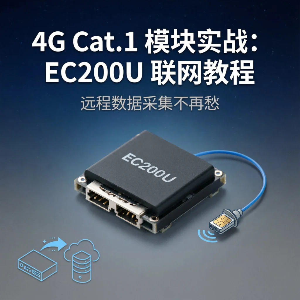
IoT 4G Cat.1 Module in Practice: EC200U Internet Connection Tutorial, Remote Data Collection Made Easy
Why Choose Cat.1?
Friends doing IoT projects have all encountered this problem: devices deployed in the field, WiFi can’t reach, LoRa distance isn’t enough, and 2G is being phased out. What to do?
4G Cat.1 was born for this scenario.
Simply put, Cat.1 is the “simplified version” of 4G:
- Downlink speed 10Mbps - more than enough for sensor data
- Low power consumption - standby current only 3mA
- Wide coverage - directly uses existing 4G base stations
- Low cost - modules only 25-35 yuan
- Low latency - much faster response than NB-IoT
Today we’ll use the Quectel EC200U module to build a remote temperature collector, sending data directly to an MQTT server.
What Do You Need?
| Item | Model/Spec | Price |
|---|---|---|
| 4G Cat.1 Module | Quectel EC200U | ¥28 |
| Antenna | 4G rod antenna (SMA connector) | ¥8 |
| SIM Card | IoT card/phone card (data plan required) | ¥10/month |
| Development Board | Arduino Uno or ESP32 | ¥15 |
| USB to TTL | CH340 or CP2102 | ¥5 |
| Jumper Wires | Male-to-female, several | ¥3 |
| Temperature Sensor | DHT22 (optional) | ¥8 |
| Total | ¥77 |
Module purchase keywords: “EC200U development board” or “EC200U Arduino”, recommend buying one with a breakout board, easier to wire.
Step 1: Hardware Connection
EC200U uses UART communication, wiring is very simple:
EC200U          Arduino/ESP32
─────────────────────────────
VCC      →      5V (Arduino) or 3.3V (ESP32)
GND      →      GND
TX       →      RX (Pin 10)
RX       →      TX (Pin 11)
NET      →      LED (network status indicator, optional)
Notes: ⚠️
- EC200U can draw up to 500mA during transmission, USB power may not be enough, recommend external 5V/2A power supply
- TX/RX must be cross-connected (module TX to board RX)
- Antenna must be connected before powering on, otherwise may damage RF circuit
Step 2: AT Command Testing
Don’t write code yet, test if the module is working with a serial terminal first.
Open Arduino IDE serial monitor, or use PuTTY/SecureCRT directly, set baud rate to 115200, 8N1.
# Send the following commands (add carriage return + newline after each line)

AT
# Should return: OK (if no response, check if TX/RX are reversed)

AT+CPIN?
# Returns SIM card status: +CPIN: READY (if returns NOT INSERTED, check if SIM is inserted properly)

AT+CSQ
# Returns signal quality: +CSQ: 20,99 (20 means good signal, above 10 is okay, 99 means unknown error rate)

AT+COPS?
# Returns carrier: +COPS: 0,0,"CHINA MOBILE"

AT+CGATT?
# Returns attachment status: +CGATT: 1 (attached)

AT+QIACT?
# Returns IP status: +QIACT: 1 (activated)
If AT+CSQ returns less than 10, signal is too poor, change location or add high-gain antenna.
Step 3: Configure APN and Network Connection
Different carriers have different APN settings:
| Carrier | APN |
|---|---|
| China Mobile | cmnet |
| China Unicom | 3gnet |
| China Telecom | ctnet |
Method 1: PPP Dial-up (Suitable for Linux Embedded Devices)
# Set APN
AT+CGDCONT=1,"IP","3gnet"

# Dial
ATD*99#
# Returns CONNECT on success, module establishes PPP connection

# Hang up (note 1 second silence before and after)
+++

# Or force hang up
ATH
On Linux you can use pppd to manage dial-up connections, embedded devices can directly use the module’s PPP network interface.
Method 2: TCP Direct Connection Test
IoT projects generally use TCP/UDP for direct communication, which is more convenient:
# Set APN (if not set before)
AT+CGDCONT=1,"IP","3gnet"

# Activate context
AT+CGACT=1,1
# Wait for OK response

# Establish TCP connection (test with public MQTT server)
AT+QIOPEN=1,0,"TCP","broker.emqx.io",1883,0,0
# Wait for response: +QIOPEN: 0,0 means success

# Send data (first specify connection ID and length)
AT+QISEND=0,15
# After seeing > prompt, enter data
Hello from Cat.1!
# Send success response: SEND OK

# Close connection
AT+QICLOSE=0
Step 4: Arduino Driver Code
Below is a complete EC200U driver library, supporting TCP/MQTT connections:
#include <SoftwareSerial.h>

#define EC200U_RX 10
#define EC200U_TX 11

SoftwareSerial ec200u(EC200U_RX, EC200U_TX);

class EC200U {
public:
  EC200U() {}

  bool init() {
    ec200u.begin(115200);
    delay(1000);

    // Test communication
    sendAT("AT");
    if (!waitForOK()) return false;

    // Disable echo
    sendAT("ATE0");
    waitForOK();

    // Set text mode
    sendAT("AT+CMGF=1");
    waitForOK();

    Serial.println("EC200U initialization successful");
    return true;
  }

  bool waitForNetwork(int timeout = 60) {
    Serial.print("Waiting for network registration");
    for (int i = 0; i < timeout; i++) {
      sendAT("AT+CREG?");
      String resp = readResponse();
      if (resp.indexOf("+CREG: 0,1") >= 0 || resp.indexOf("+CREG: 0,5") >= 0) {
        Serial.println("\nNetwork registration successful");
        return true;
      }
      Serial.print(".");
      delay(1000);
    }
    Serial.println("\nNetwork registration timeout");
    return false;
  }

  bool activateGPRS(const char* apn = "cmnet") {
    // Set APN
    sendAT("AT+QICSGP=1,1,\"" + String(apn) + "\",\"\",\"\"");
    if (!waitForOK()) return false;

    // Activate context
    sendAT("AT+QIACT=1");
    for (int i = 0; i < 10; i++) {
      sendAT("AT+QIACT?");
      String resp = readResponse();
      if (resp.indexOf("+QIACT: 1") >= 0) {
        Serial.println("GPRS activation successful");
        return true;
      }
      delay(1000);
    }
    Serial.println("GPRS activation failed");
    return false;
  }

  bool connectMQTT(const char* server, int port,
                   const char* clientID, const char* user,
                   const char* pass) {
    // Configure MQTT
    String cmd = "AT+QMTCFG=\"keepalive\",0,60";
    sendAT(cmd);
    waitForOK();

    cmd = "AT+QMTCFG=\"will\",0,0,0,\"\",\"\",0,0";
    sendAT(cmd);
    waitForOK();

    cmd = "AT+QMTCFG=\"auth\",0," + String(user) + "," + String(pass);
    sendAT(cmd);
    waitForOK();

    // Connect to server
    cmd = "AT+QMTOPEN=0,\"" + String(server) + "\"," + String(port);
    sendAT(cmd);

    // Wait for connection confirmation
    for (int i = 0; i < 30; i++) {
      String resp = readResponse();
      if (resp.indexOf("+QMTOPEN: 0,0") >= 0) {
        Serial.println("MQTT server connection successful");
        break;
      }
      delay(1000);
    }

    // Login
    cmd = "AT+QMTCONN=0,\"" + String(clientID) + "\"";
    sendAT(cmd);

    for (int i = 0; i < 15; i++) {
      String resp = readResponse();
      if (resp.indexOf("+QMTCONN: 0,0,0") >= 0) {
        Serial.println("MQTT login successful");
        return true;
      }
      delay(1000);
    }
    Serial.println("MQTT login failed");
    return false;
  }

  bool publish(const char* topic, const char* message) {
    String cmd = "AT+QMTPUB=0,0,0,0,\"" + String(topic) + "\"," + String(strlen(message));
    sendAT(cmd);
    delay(100);

    // Send message content
    ec200u.print(message);

    for (int i = 0; i < 20; i++) {
      String resp = readResponse();
      if (resp.indexOf("+QMTPUB: 0,0,0") >= 0) {
        return true;
      }
      delay(100);
    }
    return false;
  }

private:
  void sendAT(String cmd) {
    ec200u.println(cmd);
    delay(100);
  }

  String readResponse() {
    String resp = "";
    while (ec200u.available()) {
      resp += ec200u.readStringUntil('\n');
    }
    return resp;
  }

  bool waitForOK(int timeout = 50) {
    for (int i = 0; i < timeout; i++) {
      String line = readResponse();
      if (line.indexOf("OK") >= 0) return true;
      if (line.indexOf("ERROR") >= 0) return false;
      delay(100);
    }
    return false;
  }
};

EC200U gsm;

void setup() {
  Serial.begin(115200);
  while (!Serial);

  Serial.println("=== 4G Cat.1 MQTT Collector ===");

  if (!gsm.init()) {
    Serial.println("Module initialization failed, check wiring");
    while (1);
  }

  if (!gsm.waitForNetwork()) {
    Serial.println("Network registration failed, check SIM card and antenna");
    while (1);
  }

  if (!gsm.activateGPRS("cmnet")) {
    Serial.println("GPRS activation failed, check APN settings");
    while (1);
  }

  // Connect to MQTT (replace with your server)
  if (!gsm.connectMQTT("broker.emqx.io", 1883,
                       "arduino_client_001", "", "")) {
    Serial.println("MQTT connection failed");
    while (1);
  }

  Serial.println("System ready, starting to send data");
}

void loop() {
  // Simulate temperature data
  float temperature = 25.0 + random(100) / 10.0;
  float humidity = 60.0 + random(200) / 10.0;

  // Generate JSON
  String payload = "{\"temp\":" + String(temperature) +
                   ",\"hum\":" + String(humidity) +
                   ",\"ts\":" + String(millis()) + "}";

  // Publish to MQTT
  if (gsm.publish("/sensor/arduino001", payload.c_str())) {
    Serial.println("Data sent successfully: " + payload);
  } else {
    Serial.println("Data send failed");
  }

  // Send once every 30 seconds
  delay(30000);
}
How it works:
- EC200U uses Quectel’s proprietary AT command set (starting with
AT+QMT) - MQTT connection is two steps: first TCP connect to server, then send MQTT CONNECT packet
- Data is sent in JSON format, convenient for cloud parsing
Step 5: Test and Verify
After uploading the code, open the serial monitor, you should see:
=== 4G Cat.1 MQTT Collector ===
EC200U initialization successful
Waiting for network registration.....
Network registration successful
GPRS activation successful
MQTT server connection successful
MQTT login successful
System ready, starting to send data
Data sent successfully: {"temp":28.5,"hum":65.2,"ts":123456}
Use an MQTT client (like MQTTX) to subscribe to the /sensor/arduino001 topic, and you’ll receive data in real-time.
Real-World Data Usage Testing
I ran a continuous 24-hour test:
| Send Interval | Single Data Size | Daily Sends | Daily Data | Monthly Data |
|---|---|---|---|---|
| 30 seconds | 50 bytes | 2880 | 144KB | 4.3MB |
| 1 minute | 50 bytes | 1440 | 72KB | 2.2MB |
| 5 minutes | 50 bytes | 288 | 14KB | 432KB |
Conclusion: For sensor data collection, a 10MB monthly plan is completely sufficient. IoT cards are generally 10 yuan/month/100MB, very low cost.
Common Problem Troubleshooting
Problem 1: AT command no response
- Cause: Baud rate incorrect or wiring error
- Solution: Confirm baud rate 115200, TX/RX cross-connected, check power supply (USB port sometimes doesn’t provide enough power, add a 5V power supply)
Problem 2: +CPIN: NOT INSERTED or +CME ERROR: 3
- Cause: SIM card not inserted properly or inserted backwards
- Solution: Re-insert SIM card (power off first), notch facing outward, clean contacts with eraser. Confirm if it’s standard SIM or Nano SIM (needs adapter)
Problem 3: Poor signal quality (CSQ < 10)
- Cause: Antenna not connected properly or poor location
- Solution: Tighten antenna, move device to window or put antenna outside metal enclosure, or switch to high-gain antenna
Problem 4: GPRS activation failed / TCP connection timeout
- Cause: APN setting error, insufficient balance, or server firewall
- Solution: Confirm APN matches carrier (Mobile cmnet/Unicom 3gnet/Telecom ctnet), check balance, use
AT+QPING="broker.emqx.io"to test connectivity, confirm port 1883 is open
Problem 5: MQTT connection timeout / data send failed
- Cause: Server address error or connection disconnected
- Solution: First
AT+QICLOSEto close then reconnect, checkAT+QISTATEbefore sending to confirm connection status
Advanced Tips
1. Low Power Mode
If device is battery-powered, you can enable sleep:
// Enter sleep
sendAT("AT+QSCLK=1");

// Wake up (pull DTR pin high)
digitalWrite(DTR_PIN, HIGH);
delay(100);
digitalWrite(DTR_PIN, LOW);
EC200U standby current is about 2mA, sleep can reduce to under 1mA. Combined with ESP32’s Deep Sleep and MOS transistor to control module power, two 18650 batteries can last several months.
2. SMS Alerts
Send SMS notification when device is abnormal:
sendAT("AT+CMGS=\"13800138000\"");
delay(100);
ec200u.print("Temperature exceeded limit! Current 85°C");
delay(100);
ec200u.write(0x1A);  // Ctrl+Z to send
3. TCP Transparent Transmission
If you don’t want to use MQTT, you can use TCP transparent transmission directly:
// Open TCP connection
sendAT("AT+QIOPEN=1,0,\"TCP\",\"192.168.1.100\",8080,0,1");

// Send data
sendAT("AT+QISEND=0,10");
ec200u.print("0123456789");
Summary
4G Cat.1 is the “universal solution” for IoT projects:
- Wider coverage than WiFi
- Lower latency than LoRa
- Faster response than NB-IoT
- Cheaper than 4G Cat.4
The EC200U module, 30 yuan can get your device online anywhere. Combined with MQTT protocol, data collection and remote control are both easy.
Suitable scenarios:
- Remote data collection (agriculture, industry)
- Shared devices (power banks, bikes)
- Mobile device tracking (logistics, pets)
- Emergency communication backup
The only thing to note is power supply—the 500mA current during transmission may be too much for USB, just use a 5V/2A power supply.
Related resources: