 IoT
IoT A Deep Dive into the Modbus Protocol
Modbus is a serial communication protocol built on a master-slave network architecture. In the 1970s, Modicon developed this protocol to interconnect its own programmable logic controllers (PLCs). The protocol has since seen widespread adoption and is now one of the de facto industrial communication standards.
The Modbus protocol defines standards for the physical and data-link layers of serial communication. At the physical layer, Modbus supports a variety of hardware interfaces, including RS-232, RS-485, RS-422, and Ethernet, allowing data transmission over different media. At the data-link layer, Modbus specifies message framing and the communication process. Two data formats are supported: RTU and ASCII.
A Modbus network uses a single-master, multi-slave topology. Only one master device sits on the communication bus, and it can address up to 247 slave devices. The master sends requests; each slave processes the request and returns a response, completing the exchange. The master can also broadcast a message to all slaves.
Modbus is widely used in industrial environments, especially in industrial automation systems, where large numbers of intelligent devices connect and communicate via Modbus. These devices include PLCs, sensors, and HMIs. Compared with other communication protocols, Modbus is simpler, more efficient, and more stable and reliable, making it an indispensable communication standard in industrial control systems.
The Modbus Protocol
Modbus RTU
The Modbus RTU format is used for serial communication and is the most common implementation of Modbus. RTU uses a compact binary representation to transmit protocol data. After the command/data fields, an RTU frame appends a Cyclic Redundancy Check (CRC) for error detection, ensuring data integrity. An RTU message must be transmitted as a continuous stream with no inter-character gaps. Messages are delimited by idle (silent) periods.
| Start | Address | Function Code | Data | CRC | End |
|---|---|---|---|---|---|
| Idle ≥ 28 bits | 8 bits | 8 bits | N×8 bits | 16 bits | Idle ≥ 28 bits |
Modbus ASCII
The Modbus ASCII format is also used for serial communication but encodes protocol data as ASCII characters. It uses a Longitudinal Redundancy Check (LRC) for error detection. An ASCII frame begins with a colon (”:”) and ends with a carriage return / line feed (CR/LF). The ASCII format is typically used during system debugging.
| Start | Address | Function Code | Data | LRC | End |
|---|---|---|---|---|---|
| : | 2 chars | 2 chars | N chars | 2 chars | CR, LF |
Modbus TCP/IP
Modbus TCP/IP is the implementation of the Modbus protocol stack over TCP/IP networks. It encapsulates Modbus ADUs inside TCP segments. TCP/IP provides a reliable end-to-end connection and routing, so Modbus TCP/IP can carry Modbus traffic across networks. A connection is initiated by the client, which specifies the server’s IP address and port number; the well-known port is 502. Once the connection is established, the client sends requests using Modbus function codes, and the server returns response data.
| Transaction ID | Protocol ID | Length | Unit ID | Function Code | Data |
|---|---|---|---|---|---|
| 2 bytes | 2 bytes | 2 bytes | 1 byte | 1 byte | n bytes |
Operating Modes
-
Master Query — In a Modbus network, only the master is allowed to initiate queries. The master sends a query request to a slave to read or write data. The request contains the target slave address, function code, data address, and other parameters. This is the master query operation.
-
Slave Response — When a slave receives a query from the master, it performs the requested operation and returns a response. The response carries the same address and function code fields, along with the requested data or a status indicator. This is the slave response operation.
-
Broadcast — The master can broadcast by setting the address field to 0, sending a message to all slaves. Slaves do not reply to broadcast messages. Broadcasting is used for batch command control from the master.
Function Codes
Modbus defines a rich set of function codes, each representing a different type of communication service. The function codes are defined as follows:
| Function Code | Hex | Description | Type |
|---|---|---|---|
| FC01 | 0x01 | Read Coil Status | Single-bit access |
| FC02 | 0x02 | Read Discrete Input Status | Single-bit access |
| FC05 | 0x05 | Write Single Coil | Single-bit access |
| FC15 | 0x15 | Write Multiple Coils | Single-bit access |
| FC03 | 0x03 | Read Holding Registers | Double-byte access |
| FC04 | 0x04 | Read Input Registers | Double-byte access |
| FC06 | 0x06 | Write Single Register | Double-byte access |
| FC16 | 0x10 | Write Multiple Registers | Double-byte access |
| FC22 | 0x16 | Read/Write Multiple Registers: combined read and write of multiple holding registers | Double-byte access |
| FC23 | 0x17 | Read/Write Coils: combined read and write of coil status | Double-byte access |
| FC24 | 0x18 | Read FIFO Queue: read data from a slave FIFO queue | Double-byte access |
| FC20 | 0x14 | Read File Record: read memory and input registers into a file | File access |
| FC21 | 0x15 | Write File Record: write memory or output registers from a file | File access |
| FC08 | 0x08 | Diagnostics: check slave communication status | Diagnostics |
| FC11 | 0x0B | Get Comm Event Counter: retrieve Modbus statistics | Diagnostics |
| FC12 | 0x0C | Get Slave Servo Parameters: read servo motor parameter configuration | Diagnostics |
| FC17 | 0x11 | Read Device Identification: retrieve device identification information | Diagnostics |
These function codes cover the full range of Modbus communication services and enable remote monitoring and control of industrial equipment.
Register Types Explained
Coil Status
Coil status registers represent the on/off state of a device or process, typically corresponding to relay outputs. One coil represents one discrete (binary) value. Reading coils yields the current switch state; writing coils changes it.
Discrete Input Status
Discrete input registers represent the on/off state of input signals to a device or process — essentially, binary inputs. Reading discrete inputs returns the state of those binary inputs.
Holding Registers
Holding registers store numeric parameters, configuration values, and similar data for a device. Unlike coils, a holding register holds a 16-bit value. Reading a holding register retrieves the parameter value; writing one modifies it.
Input Registers
Input registers correspond to analog inputs of a device or process and also hold 16-bit values. Reading input registers yields real-time values of process variables and analog input channels.
Holding Registers vs. Input Registers
The differences between holding registers and input registers:
- Data Attributes
Data in holding registers is typically configurable and writable — for example, device parameters and control setpoints. The master can write to them.
Data in input registers is usually read-only, used to convey real-time measurements or monitoring data. The master cannot modify it.
- Data Flow Direction
Holding registers are primarily used to transfer control setpoints from the master to the slave. Data flows from master to slave.
Input registers are primarily used to upload monitoring data from the slave to the master. Data flows from slave to master.
- Data Characteristics
Data in holding registers is configurable and changes occasionally. Data in input registers is typically continuously changing real-time data.
- Typical Use Cases
Holding registers are commonly used for parameter configuration; input registers are commonly used for process monitoring.
Data Structure
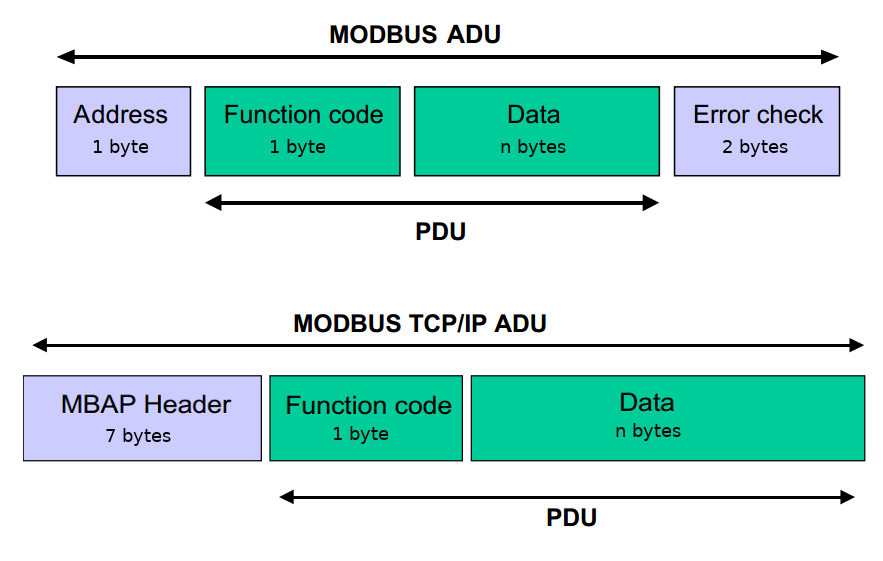
Modbus data structures are divided into two parts:
PDU (Protocol Data Unit)
The PDU is the portion of a Modbus message that carries the actual function code and data. It consists of:
-
Function Code field: indicates the action to be performed, 1 byte.
-
Data field: variable length, up to 252 bytes. Contains parameters such as data address and quantity.
ADU (Application Data Unit)
The ADU is the complete Modbus message frame. Built on top of the PDU, it adds addressing and error-checking fields:
-
Address field: contains the slave address, 1 byte.
-
PDU: function code and data.
-
Error check: 2-byte CRC for RTU; LRC for ASCII.
-
Frame delimiters: ASCII format includes start and end characters.
By combining the PDU and ADU, Modbus can flexibly represent different request/response messages. This data structure is well suited to serial communication and the master-slave model, and is one of the defining characteristics of the Modbus protocol.
Common Applications
As industrial control networks have evolved, the Modbus protocol has been adopted ever more widely. Key application areas include:
-
PLC Networking — Multiple PLCs form a Modbus network over an RS-485 bus, enabling centralized factory-automation monitoring and data acquisition.
-
Instrument Data Acquisition — Modbus is used to read real-time data from smart instruments such as temperature/humidity sensors, pressure transmitters, and power meters, feeding process monitoring systems.
-
VFD and Drive Control — A host computer sends frequency, start/stop, and other control commands to variable-frequency drives over Modbus, and reads back operating status and fault information.
-
Building Automation Systems (BAS) — HVAC, lighting, elevators, and other subsystems are integrated into a unified management platform via Modbus, enabling intelligent building control.
-
Power System Monitoring — In substations and distribution rooms, Modbus is used to acquire parameters from relay protection devices and smart meters, enabling remote monitoring and fault diagnosis.
-
Industrial IoT Gateways — Modbus devices connect to modern IoT platforms (MQTT, OPC UA, etc.) via protocol-conversion gateways, enabling cloud-based analytics and remote O&M for industrial data.
In summary, Modbus is a mature and stable industrial communication protocol with a very broad range of applications. As the Industrial Internet continues to grow, the Modbus protocol will play an increasingly important role in driving the intelligentization of industrial systems.