 Embedded Development
 ESP32 Practical Guide: Common Troubleshooting + Marlin Firmware + OpenAI SDK Practice
Introduction
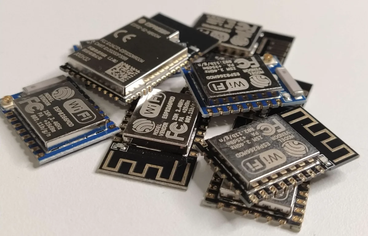
ESP32 is a low-cost, low-power system-on-chip from Espressif, integrating Wi-Fi and dual-mode Bluetooth, with a dual-core processor clocked up to 240 MHz. It’s a popular choice for smart home, IoT prototypes, and 3D printer control boards. This article covers three major topics: common troubleshooting, Marlin firmware installation, and OpenAI real-time embedded SDK practice, helping you go from “pitfalls” to “hands-on” in one step.
Part 1: ESP32 Common Troubleshooting
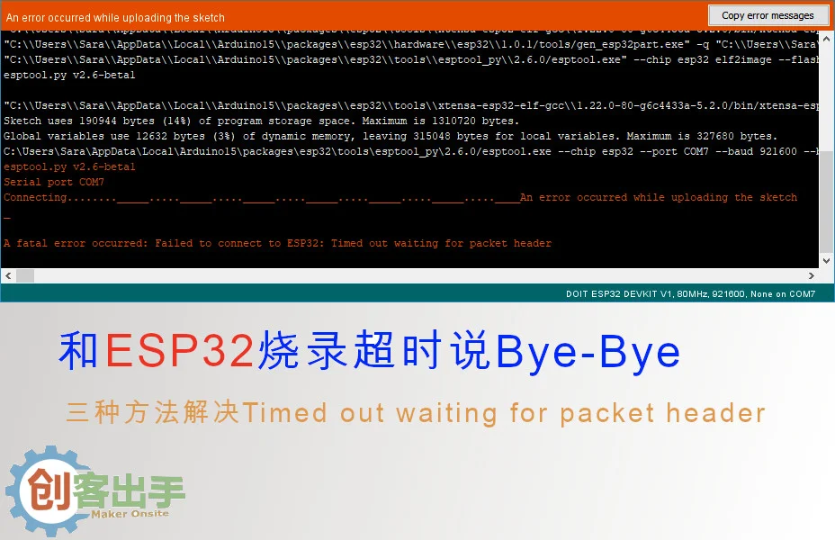
1.1 Auto-Flash Timeout (Timed out waiting for packet header)
Almost everyone who has used ESP32 has experienced flash timeout. There are three main reasons for this:
- Poor quality USB-UART bridge chip: Cheap CH340 has less transmission stability than CP2102
- Poor quality USB data cable: Low-quality cables have insufficient power supply or signal degradation
- RC delay circuit parameter deviation: Switching time between EN and GPIO0 is too short, chip cannot correctly identify download mode
Auto-Flash Principle
ESP32 connects USB and chip serial port through USB-UART Bridge, GPIO0 level determines download/run mode:
| Mode | GPIO0 Level |
|---|---|
| UART download mode | Low |
| Flash run mode | High |
During flashing, RTS goes high first, DTR goes low, triggering GPIO0 pull-down first, then EN pull-down, then both pull-up together, completing download mode switch. The RC delay circuit on the board increases the time interval between the two pull-downs. Timeout often occurs because the switching time is too short. The official recommendation is to directly press the BOOT/IO0 button to enter download mode.
Flash Chip Comparison
- CP2102: Fast, small, stable, 8-10 yuan
- CH340: Slightly slower, slightly less stable, 1-2 yuan
NodeMCU V2 uses CP2102, V3 switched to CH340, both cost and supply chain factors may be reasons.
Solution 1: Lower Flash Speed
The simplest solution is to lower the flash speed to 115200, which has a higher success rate. Adjust the baud rate in Arduino IDE or PlatformIO flash settings.
Solution 2: Manually Enter Flash Mode
Since the auto-flash circuit triggers EN pull-down first then GPIO0 pull-down signal, we can trigger it manually:
- Hold down the BOOT/FLASH/IO0 button on the board
- Press the EN/RST reset button then release
- Release the BOOT button, at this point ESP32 has entered download mode, then flash
Solution 3: Add External Capacitor (More Effective for WROOM Series)
Add a 10μF capacitor between EN and GND. The principle is to increase the time interval between EN and GPIO0 being pulled low. This method works but affects appearance, only for reference.
Summary: If none of the above 3 methods solve the problem, it’s recommended to choose a high-quality ESP32 development board, especially choose boards using CP210X series chips.
1.2 macOS Upgrade “python” executable file not found
macOS 12.3 removed Python 2, but Arduino ESP32 depends on Python interpreter, building will report error "python": executable file not found in $PATH.
Solution: Change Arduino configuration to python3. Taking esp32 2.0.2 version as example, modify file ~/Library/Arduino15/packages/esp32/hardware/esp32/2.0.2/platform.txt, change:
tools.gen_esp32part.cmd=python "{runtime.platform.path}/tools/gen_esp32part.py"to:
tools.gen_esp32part.cmd=python3 "{runtime.platform.path}/tools/gen_esp32part.py"1.3 “Brownout detector was triggered” Error
This error occurs because the chip detected system voltage below threshold (brownout voltage), it will automatically shut down the processor to preserve memory contents and avoid damage. Common causes:
- Poor quality USB data cable, insufficient power supply
- USB interface has limited power capacity, cannot meet ESP32 peak current demand
- External load consumes too much power, causing voltage drop
This can usually be solved by replacing with a better quality data cable. If it still can’t be solved after replacement, you can disable brownout detection through code:
#include "soc/soc.h"
#include "soc/rtc_cntl_reg.h"

void setup() {
  WRITE_PERI_REG(RTC_CNTL_BROWN_OUT_REG, 0); // Disable brownout detection
  // Your other initialization code...
}
1.4 Core dump flash config is corrupted Error
This error may be caused by internal SPI quality issues, changing Flash Mode from default QIO to DIO may solve it. ESP32 has four flash modes:
| Mode | Speed | Pins | Features |
|---|---|---|---|
| QIO | Fastest | 4 pin address+data | Default high speed |
| QOUT | 15% slower | 4 pin data | — |
| DIO | 45% slower | 2 pin address+data | Better compatibility |
| DOUT | 55% slower | 2 pin data | Most stable |
Part 2: Installing Marlin 3D Printer Firmware on ESP32
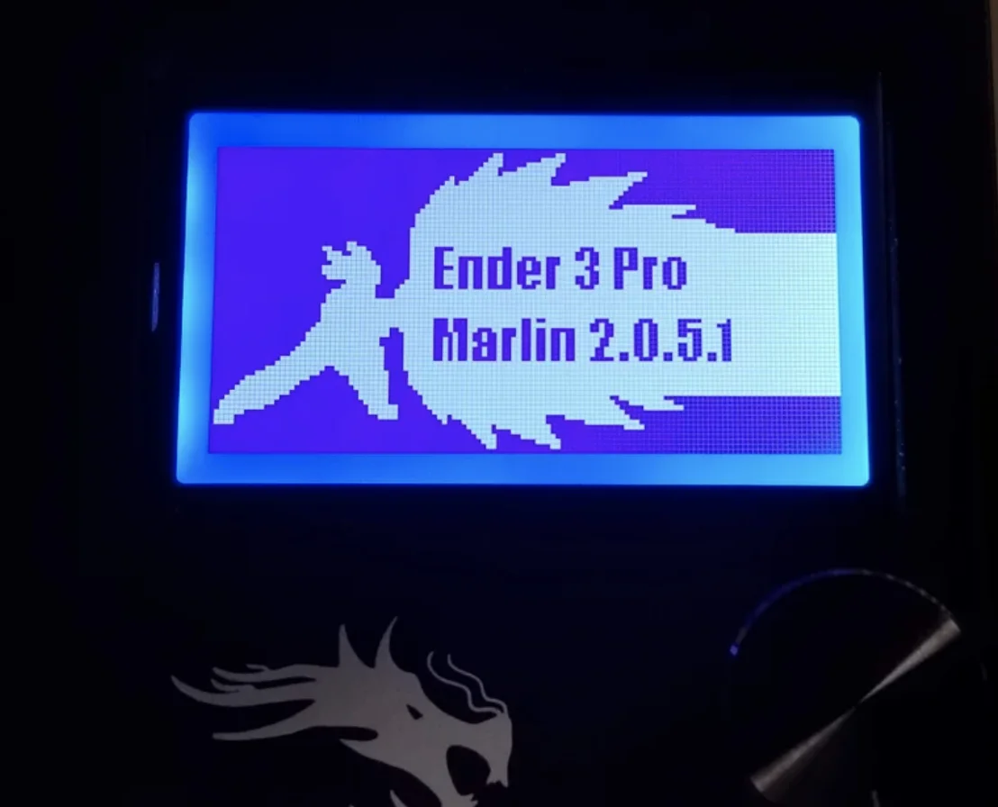
Marlin 2.0.x started supporting ESP32 series 3D printer mainboards, using it to control printers can achieve wireless monitoring and remote control.
2.1 Development Tools
It’s recommended to use VS Code + PlatformIO IDE, with a friendly interface and complete build task management, the experience far exceeds Arduino IDE.
2.2 Install ESP32 Driver
Before uploading code, you need to install ESP32’s USB-UART driver. For CP2102 chip, download from Silicon Labs official website. After installation, you can see the device in PlatformIO → PIO Home → Devices → Refresh.
2.3 Get Marlin Source Code
You need to pull the latest development branch to fully use ESP3D Web interface:
git clone -b bugfix-2.0.x https://github.com/MarlinFirmware/Marlin.gitAfter opening VS Code, confirm the branch in the lower left corner points to bugfix-2.0.x.
2.4 Configure and Compile
After opening the Marlin project in VS Code, configure according to the following steps:
- Open
platformio.ini, changedefault_envstoesp32 - Modify the mainboard type in
Configuration.hto the corresponding ESP32 mainboard (such asBOARD_MRR_ESPA) - Configure WiFi parameters (SSID and password)
- Adjust stepper motor, temperature sensor and other hardware parameters as needed
- Execute Build to compile the code
- Use Upload and Monitor to upload firmware and view serial output
2.5 Configure ESP3D Web Interface
After WiFi is connected normally, find ESP32’s IP address in the router, open it directly with a browser. If the page shows index.html.gz missing, you need to download from ESP3D repository and upload to ESP32’s file system. ESP3D supports printer control, G-code printing, WiFi settings and AP mode configuration.
2.6 ESP32 Pin Wiring Reference
Pin definitions can be found in Marlin/src/pins/esp32/pins_ESP32.h, but some numbers greater than 100 in the original file may be inaccurate. It’s recommended to refer to the actual mainboard (such as MRR ESPA) pin definitions for configuration.
Part 3: Using ESP32 with OpenAI Real-time Embedded SDK
3.1 Introduction
OpenAI Real-time Embedded SDK allows microcontrollers like ESP32 to use the real-time API to achieve voice interaction. In the past, smart devices could only play preset sounds, this SDK enables devices to “understand” user voice and respond.
Main features: Real-time voice interaction, natural language processing, two-way dialogue, low development threshold - basic configuration can access AI features.
3.2 Architecture Design
The SDK’s core idea is to combine edge computing with cloud AI:
- Edge computing: ESP32 is responsible for collecting audio, connecting to the cloud via WiFi
- Cloud AI: OpenAI real-time API handles speech recognition, natural language understanding and speech synthesis
- Bidirectional data flow: Real-time audio transmission through WebRTC
Key technologies: WebRTC (real-time audio), Protobufc (data serialization), ESP-IDF (development framework).
3.3 Development Environment Configuration
Hardware support: SDK is mainly tested on ESP32-S3 and Linux, official development boards are recommended.
# Install protobuf compiler
sudo apt install protobuf-c-compiler

# Set environment variables
export WIFI_SSID="YourWiFiName"
export WIFI_PASSWORD="YourWiFiPassword"
export OPENAI_API_KEY="YourAPIKey"

# Set target platform
idf.py set-target esp32s3   # ESP32-S3
idf.py set-target linux      # Linux (desktop testing)
3.4 Code Flow Example
Refer to official example:
- Initialize WiFi: Connect to specified network
- Initialize audio: Configure I2S interface and sampling rate
- Establish connection: Connect to OpenAI API through WebRTC/WebSocket
- Audio transmission: Send collected audio, receive and play returned audio
- Exception handling: Handle connection disconnection and error retry
3.5 Compile and Flash
# Compile
idf.py build

# Flash to ESP32-S3
sudo -E idf.py flash

# Linux platform run directly
./build/main
3.6 Common Issues
| Problem | Solution |
|---|---|
| Network connection failed | Check if WiFi signal is stable, SSID and password are correct |
| API key error | Confirm OpenAI API key is correctly set as environment variable |
| Compilation error | Ensure all dependencies are installed (protoc, protobufc, etc.) |
| Speech recognition inaccurate | Test in quiet environment, reduce environmental noise interference |
| Device response delay | Optimize network connection, use lower latency network |
Note: The SDK’s main logic runs in the cloud, the device only needs to be responsible for audio collection and transmission, so ESP32’s computing power will not be a bottleneck.
Summary
This article covers practical knowledge in ESP32 development from three dimensions: troubleshooting methods for common issues like flash timeout and brownout detection, the complete process of Marlin 3D printer firmware installation, and voice interaction practice with OpenAI real-time embedded SDK. ESP32 is capable of everything from simple IoT prototypes to production-grade AI applications, hope this comprehensive guide helps you use it more efficiently.