 Embedded Development
 Arduino Beginner Practice: Photoresistor Detection + Serial Servo Control
When you first get an Arduino UNO, the two things you probably want to know most are: how to make the board read external signals (sensor input), and how to make the board drive external devices (actuator output).
This tutorial uses two classic beginner projects to explain both things at once:
- Photoresistor Detection: Read analog signals, observe light changes in real-time through the serial monitor
- Serial Servo Control: Enter angle numbers in the serial monitor, the servo rotates to the corresponding position
After completing these two experiments, you will have an intuitive understanding of Arduino’s digital I/O, analog input, serial communication, PWM output, and library usage.
1. Hardware You Need to Prepare
The two projects can share most of the hardware, prepare everything at once:
| Component | Quantity | Description |
|---|---|---|
| Arduino UNO (or compatible board) | 1 | With USB data cable |
| Breadboard | 1 | 830-hole or 400-hole both work |
| Photoresistor | 1 | Also called photoresistor module, bare chip or module both work |
| Regular resistors | Several | 1KΩ / 4.7KΩ / 10KΩ, used as voltage dividers |
| Servo | 1 | SG90 or MG996R both work |
| Jumper wires | Several | Prepare some male-to-male, male-to-female |
| LED (optional) | 1 | Onboard D13 already has one, can skip |
Tip: If you’re a complete beginner, it’s recommended to buy an “Arduino starter kit” directly, the above components will basically all be included.
2. Project 1: Photoresistor Detection
2.1 What is a Photoresistor?
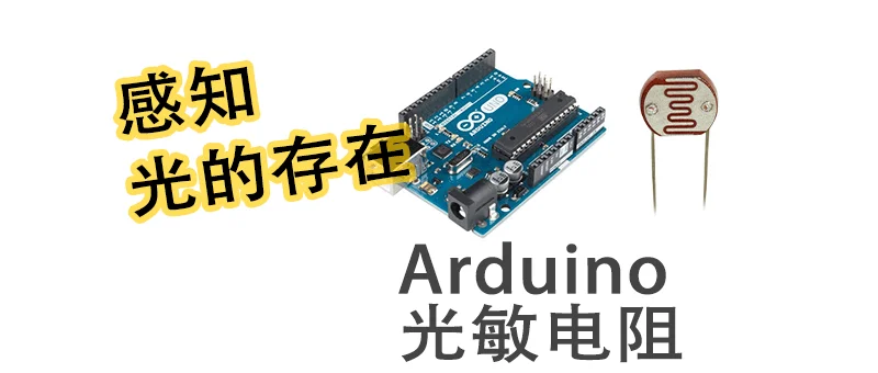
A photoresistor (Photoresistor / LDR, Light Dependent Resistor) is a component whose resistance value changes with light intensity:
- Stronger light → Lower resistance
- Weaker light → Higher resistance
Photoresistors don’t have positive and negative poles, can be directly replaced in the circuit. But note that if you want to get a larger range of numerical changes, inputting 5V works better than 3.3V.
If it’s a photodiode (Photodiode), it has the unidirectional conduction characteristic of a diode, has positive and negative poles, can be distinguished by measuring with a multimeter.
2.2 Wiring Method
Core idea: The photoresistor and a fixed resistor are connected in series to form a voltage divider circuit, the middle node is connected to Arduino’s analog input pin A5.
        5V
         │
         ├── Fixed resistor (10KΩ)
         │
         ├──────────── A5 (analog input)
         │
         ├── Photoresistor
         │
        GND
Specific wiring:
| Component Pin | Connect to |
|---|---|
| One end of photoresistor | 5V |
| Other end of photoresistor | A5 + one end of fixed resistor |
| Other end of fixed resistor | GND |
The function of the fixed resistor is to form a voltage divider with the photoresistor. Different resistance values result in different ADC reading ranges - you can try 1KΩ, 4.7KΩ, 10KΩ separately to observe which works best.
2.3 Program Code
#define AD5 A5    // Define analog pin A5
#define LED 13    // Define digital pin 13 (onboard LED)

int Intensity = 0; // Light intensity value

void setup()  // Program initialization
{
  pinMode(LED, OUTPUT);     // Set LED as output mode
  Serial.begin(9600);       // Set serial baud rate 9600
}

void loop() // Program main loop
{
  Intensity = analogRead(AD5);  // Read ADC value of analog pin A5 (0~1023)
  Serial.print("Intensity = ");
  Serial.println(Intensity);    // Serial output value, and newline
  delay(500);                   // Delay 500ms
}
2.4 Observe Serial Monitor
After uploading the program, open Arduino IDE’s Serial Monitor (shortcut Ctrl+Shift+M), baud rate select 9600.
You will see output like this:
Intensity = 720
Intensity = 715
Intensity = 312
Intensity = 298
Intensity = 680- Shine a flashlight on the photoresistor → Value increases (or decreases, depending on wiring method)
- Cover the photoresistor with your hand → Value changes in the opposite direction
analogRead() returns an integer between 01023, corresponding to 05V voltage. This is Arduino’s 10-bit ADC (analog-to-digital converter).
3. Project 2: Serial Servo Control
3.1 What is a Servo?
A servo is a motor that can precisely control rotation angle. Unlike regular DC motors, servos have built-in reduction gears and feedback circuits, can rotate to a specified angle and hold it.
Common specifications:
| Type | Angle Range | Typical Model |
|---|---|---|
| Regular servo | 0° ~ 180° | SG90, MG90S |
| Digital servo | 0° ~ 180° | MG996R |
| Continuous rotation servo | 360° continuous rotation | Modified SG90 |
3.2 Servo Pin Description
Servos usually have three wires:
| Wire Color | Function | Connect to |
|---|---|---|
| Brown / Black | Ground (GND) | Arduino GND |
| Red | Power (VCC) | Arduino 5V |
| Orange / White | Signal (IN) | Arduino D9 (PWM pin) |
Note: Digital pins marked with
~symbol on Arduino UNO support PWM (Pulse Width Modulation). The servo’s signal wire must be connected to a PWM pin (D9 or D10).
3.3 Wiring Method
Arduino UNO
┌──────────┐
│          │
│   D9 ────┼──── Servo signal wire (orange)
│   5V ────┼──── Servo power wire (red)
│  GND ────┼──── Servo ground wire (brown)
│          │
└──────────┘
Power reminder: SG90 small servo can be powered directly by Arduino’s 5V. But for high-current servos like MG996R, it’s recommended to power separately, otherwise it may burn the board or cause restarts.
3.4 Program Code
#include <Servo.h>  // Include servo library

Servo myservo;       // Create servo object

char inByte = 0;     // Single character received from serial
int angle = 0;       // Angle value
String temp = "";    // Temporary string buffer

void setup()
{
  myservo.attach(9);    // Servo signal wire connected to D9 pin
  Serial.begin(9600);   // Set serial baud rate 9600
}

void loop()
{
  // Check if serial data has arrived
  while (Serial.available() > 0)
  {
    inByte = Serial.read();      // Read one character at a time
    temp += inByte;              // Append to temporary string
  }

  if (temp != "")   // If buffer is not empty
  {
    angle = temp.toInt();       // Convert string to integer
    Serial.print("Angle: ");
    Serial.println(angle);      // Echo to serial for easy observation
  }
  temp = "";   // Clear buffer

  myservo.write(angle);  // Control servo to rotate to specified angle
  delay(100);            // Delay 100ms, wait for servo to reach position
}
3.5 Usage Method
- After uploading the program, open serial monitor (baud rate 9600)
- Enter a number between 0 and 180, for example
90 - Click Send
- The servo will immediately rotate to the corresponding angle
The servo’s valid angle range is 0° ~ 180°. Values outside the range may be ignored or cause the servo to jitter.
3.6 Program Logic Analysis
The core logic of this program is not complicated:
- Include library:
#include <Servo.h>— Arduino’s built-in servo control library - Create object:
Servo myservo;— Declare a servo instance - Bind pin:
myservo.attach(9);— Bind servo signal wire to D9 - Read serial: Read input character by character, assemble into complete string
- Convert angle:
temp.toInt()converts string to integer - Execute control:
myservo.write(angle)makes servo rotate to target angle
4. Knowledge Point Comparison of Two Projects
| Knowledge Point | Project 1: Photoresistor | Project 2: Servo Control |
|---|---|---|
| Signal Direction | Input (Sensor → Arduino) | Output (Arduino → Actuator) |
| Pin Type | Analog input (A5) | Digital PWM output (D9) |
| Core Function | analogRead() | myservo.write() |
| Communication Method | Serial output (debugging observation) | Serial input (control commands) |
| Library Usage | No additional library needed | Need #include <Servo.h> |
After completing these two experiments, you will find that Arduino programming’s basic pattern is: read sensor → process data → drive actuator. No matter what more complex projects you do later - smart car, weather station, robotic arm - the underlying logic is consistent.
5. Common Questions
Q: Photoresistor reading doesn’t change? Check if the voltage divider resistor is connected properly, confirm the photoresistor is not short-circuited. Try a different resistance value (1KΩ / 10KΩ).
Q: Servo jitters randomly, doesn’t return to position? Insufficient power is the most common cause. For large servos, please power separately, and note common ground.
Q: Serial monitor shows garbled characters?
Confirm Serial.begin() baud rate matches serial monitor settings (both are 9600).
Q: Servo can only rotate to 0° and 180°, doesn’t move at intermediate angles? Check if you entered a number within the valid range. Some cheap servos have poor precision, small angle changes are not obvious.
6. What to Learn Next?
After completing these two beginner projects, you can continue to try:
- Map photoresistor reading to servo angle (
map()function), achieving “the stronger the light, the more the servo rotates” - Add an LCD screen to display sensor values
- Try DHT11 temperature and humidity sensor, learn one-wire protocol
- Learn I2C / SPI protocols, connect more advanced sensors
Arduino’s world is vast, but the barrier to entry is indeed not high. One board, a few wires, a few dozen lines of code - you can make hardware move.