 Arduino
 Arduino Motor Driver Complete Guide: A4988 Stepper Motor + L298N DC Motor Practice
Introduction
In Arduino projects, motors are one of the most commonly used actuators. Whether it’s 3D printers, CNC engravers, or self-balancing robots, none can work without motor drivers. Arduino itself can only output weak digital signals (maximum 40mA) and cannot directly drive motors, so dedicated driver modules are needed to amplify current and control direction.
This guide will introduce two of the most commonly used motor driving solutions: A4988 driving stepper motors (precise position control) and L298N driving DC motors (speed control). Through this article, you will master the complete process from wiring, code to debugging.
Part 1: A4988 Driving Stepper Motor
Required Materials
| Name | Quantity |
|---|---|
| Arduino Uno | 1 |
| A4988 stepper motor driver module | 1 |
| 42 stepper motor (NEMA 17) | 1 |
| Breadboard | 1 |
| 9V power supply | 1 |
| Jumper wires | Several |
A4988 Module Introduction
A4988 is a microstepping stepper motor driver with built-in overcurrent protection. It can drive bipolar stepper motors, supporting up to 35V voltage and 2A/phase current. The module has a built-in potentiometer to adjust output current to prevent motor overheating.
Microstepping Configuration
The biggest highlight of A4988 is microstepping support. Through the combination of high/low levels on MS1, MS2, MS3 three pins, different stepping precision can be set:
| Mode | MS1 | MS2 | MS3 | Steps per Revolution |
|---|---|---|---|---|
| Full step | LOW | LOW | LOW | 200 |
| 1/2 step | HIGH | LOW | LOW | 400 |
| 1/4 step | LOW | HIGH | LOW | 800 |
| 1/8 step | HIGH | HIGH | LOW | 1600 |
| 1/16 step | HIGH | HIGH | HIGH | 3200 |
Taking a common 1.8° stepper motor as an example: full step mode requires 200 steps per revolution, while 1/16 microstep mode requires 3200 steps - precision improved by 16 times!
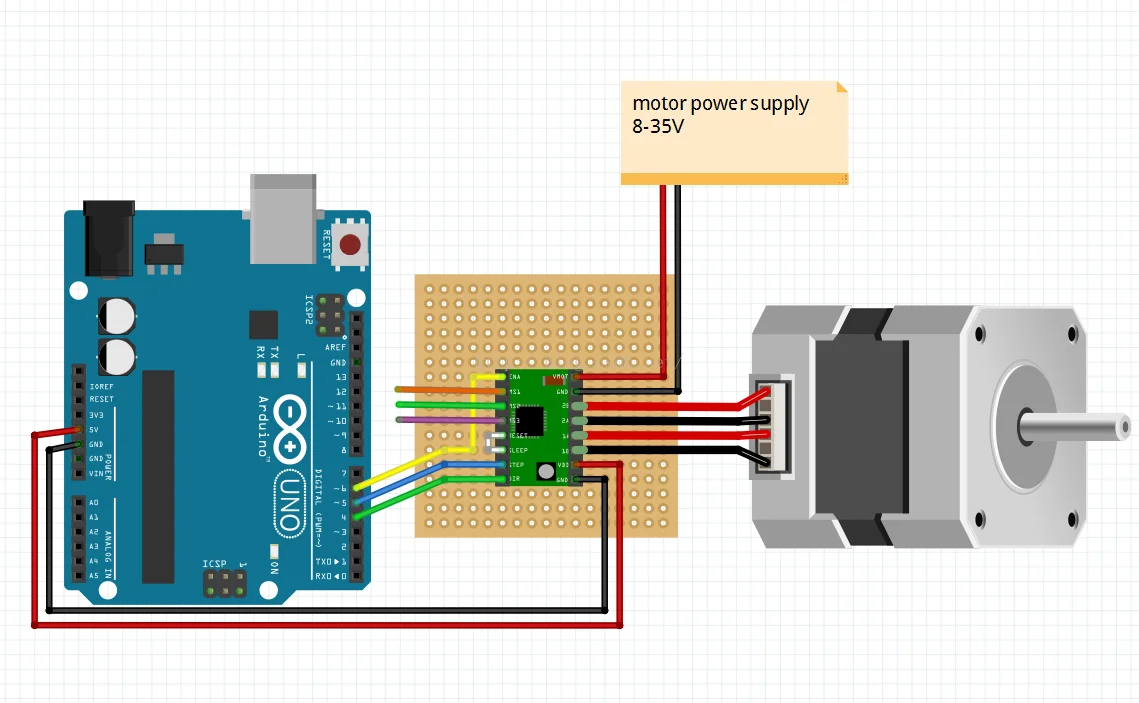
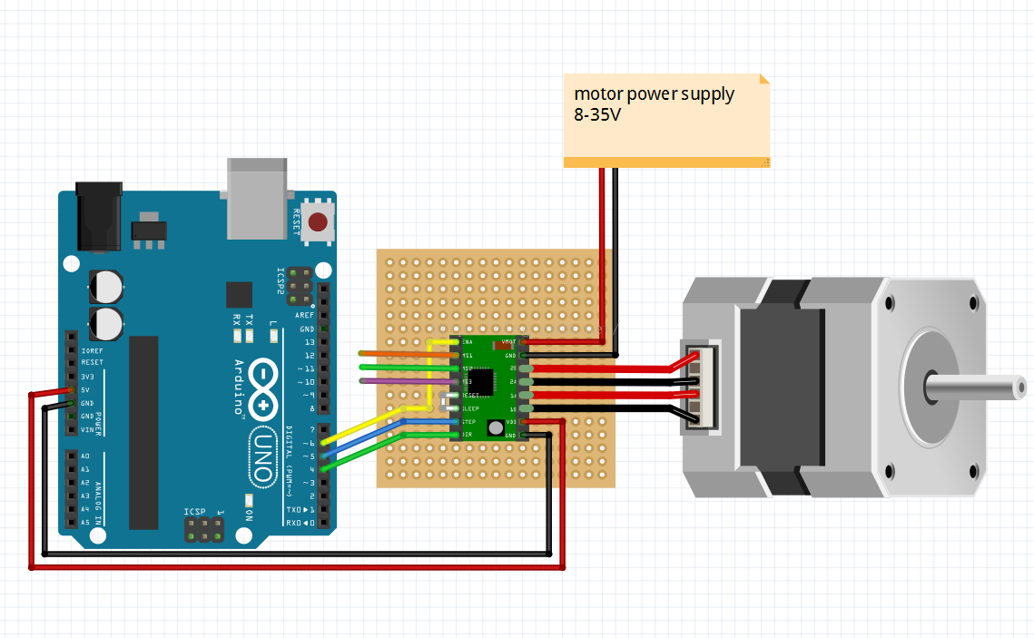
Wiring Diagram
Pin Description
| A4988 Pin | Arduino Connection | Description |
|---|---|---|
| EN (Enable) | Digital pin 6 | Active LOW, driver works when pulled low |
| STEP | Digital pin 5 | One pulse per step |
| DIR (Direction) | Digital pin 4 | HIGH for forward, LOW for reverse |
| VMOT | Power positive | 8V ~ 35V power supply |
| GND | Arduino GND | Common ground |
Complete Code
// Define pins
int stepPin = 5;
int dirPin = 4;
int enPin = 6;

void setup() {
  pinMode(stepPin, OUTPUT);
  pinMode(dirPin, OUTPUT);
  pinMode(enPin, OUTPUT);

  digitalWrite(enPin, LOW);  // Enable driver
  digitalWrite(dirPin, HIGH); // Set direction
}

void loop() {
  // Send 200 pulses, stepper motor rotates one revolution (full step mode)
  for (int i = 0; i < 200; i++) {
    digitalWrite(stepPin, HIGH);
    delayMicroseconds(500);  // Pulse high time
    digitalWrite(stepPin, LOW);
    delayMicroseconds(500);  // Pulse low time
  }

  delay(1000);  // Pause 1 second

  // Reverse direction
  digitalWrite(dirPin, LOW);

  // Rotate one more revolution
  for (int i = 0; i < 200; i++) {
    digitalWrite(stepPin, HIGH);
    delayMicroseconds(500);
    digitalWrite(stepPin, LOW);
    delayMicroseconds(500);
  }

  delay(1000);

  // Restore direction
  digitalWrite(dirPin, HIGH);
}
Key Notes
- Pulse timing: The value of
delayMicroseconds()determines rotation speed. The smaller the value, the faster the speed, but it cannot be too small causing the motor to lose steps (generally not lower than 100μs). - Current adjustment: When using for the first time, use a multimeter to measure the potentiometer, adjust the reference voltage to ensure it doesn’t exceed the motor’s rated current.
- Heat dissipation: A4988 is easy to heat up when driving large currents, it’s recommended to install a heatsink.
Part 2: L298N Driving DC Motor
Required Materials
| Name | Quantity |
|---|---|
| Arduino Uno | 1 |
| L298N motor driver module | 1 |
| DC gear motor | 2 |
| 9V battery holder | 1 |
| USB cable | 1 |
| Jumper wires | Several |
L298N Module Introduction
L298N is a dual H-bridge motor driver chip that can control two DC motors (or one stepper motor) simultaneously. It supports up to 46V voltage and 2A current output, with built-in flyback diodes for easy use.
| Module Name | Dual H-bridge motor driver module | Operating Mode | H-bridge drive (dual channel) |
|---|---|---|---|
| Operating Voltage | 5V ~ 35V | Operating Current | 2A (peak 3A) |
| Logic Voltage | 5V ~ 7V | Maximum Power | 20W |
| Drive Type | Dual H-bridge | Operating Temperature | -20℃ ~ +135℃ |
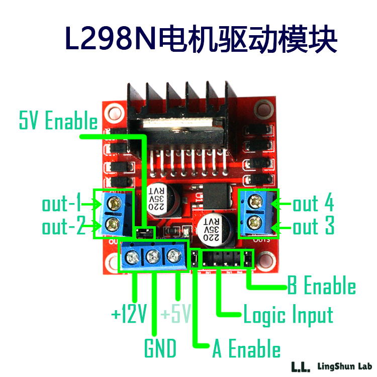
Pin Description
| Pin | Description |
|---|---|
| 12V Input | Connect to external power positive (7V-12V) |
| GND | Power negative, common ground with Arduino |
| 5V Output | Can be used as 5V power supply for Arduino |
| ENA / ENB | Enable jumpers, control channel A/B (remove for PWM speed control) |
| IN1 / IN2 | Channel A direction control |
| IN3 / IN4 | Channel B direction control |
| OUT1 / OUT2 | Connect to motor A |
| OUT3 / OUT4 | Connect to motor B |
Wiring Diagram
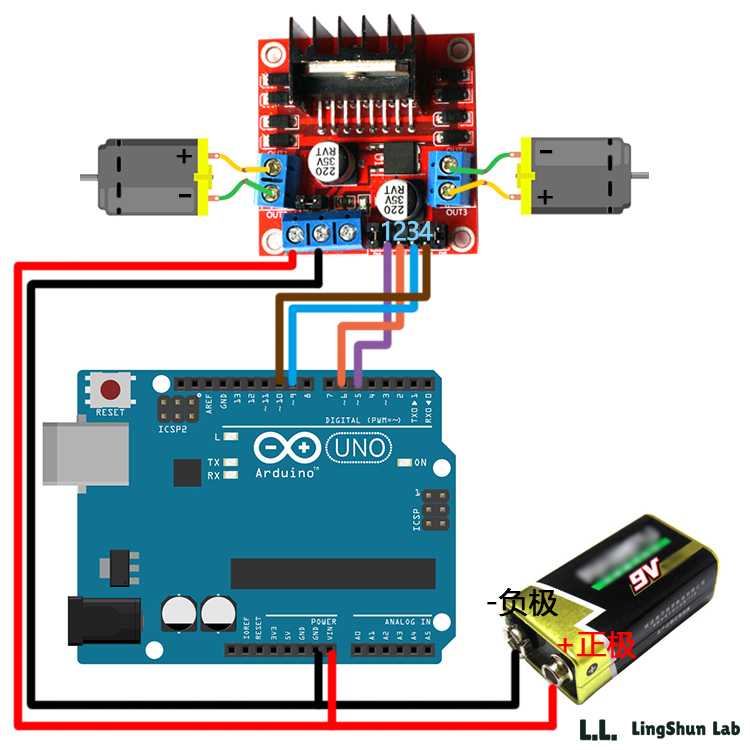
Key Notes
- Power supply: DC motors need 7V-12V external power supply. Arduino’s USB 5V current is too small to drive motors, must use independent power supply.
- PWM speed control: ENA and ENB jumpers are inserted by default, at this time motors run at full speed. For speed control, remove jumpers and connect ENA/ENB to Arduino’s PWM pins (5, 6, 9, 10).
Complete Code
// Motor A: ENA connected to pin 5, IN1 connected to pin 7, IN2 connected to pin 8
// Motor B: ENB connected to pin 6, IN3 connected to pin 9, IN4 connected to pin 10

int enA = 5;
int in1 = 7;
int in2 = 8;
int enB = 6;
int in3 = 9;
int in4 = 10;

void setup() {
  pinMode(enA, OUTPUT);
  pinMode(in1, OUTPUT);
  pinMode(in2, OUTPUT);
  pinMode(enB, OUTPUT);
  pinMode(in3, OUTPUT);
  pinMode(in4, OUTPUT);

  // Set initial speed (PWM value 0-255)
  analogWrite(enA, 150);  // Motor A medium speed
  analogWrite(enB, 200);  // Motor B faster speed
}

void loop() {
  // Motor A forward, Motor B forward
  digitalWrite(in1, HIGH);
  digitalWrite(in2, LOW);
  digitalWrite(in3, HIGH);
  digitalWrite(in4, LOW);
  delay(2000);

  // Motor A reverse, Motor B reverse
  digitalWrite(in1, LOW);
  digitalWrite(in2, HIGH);
  digitalWrite(in3, LOW);
  digitalWrite(in4, HIGH);
  delay(2000);

  // Motor A stop, Motor B stop
  digitalWrite(in1, LOW);
  digitalWrite(in2, LOW);
  digitalWrite(in3, LOW);
  digitalWrite(in4, LOW);
  delay(2000);
}
Part 3: A4988 vs L298N Comparison
| Feature | A4988 | L298N |
|---|---|---|
| Motor Type | Stepper motor | DC motor |
| Precision | High (microstepping) | Low (switch control) |
| Speed Control Method | Pulse frequency | PWM duty cycle |
| Typical Applications | 3D printers, CNC | Cars, robots |
| Drive Current | 2A/phase | 2A/bridge |
| Encoder Feedback Required | No (open-loop control) | No (no position feedback) |
Simply put: Choose A4988 + stepper motor for precise positioning, choose L298N + DC motor for high-speed rotation.
Common Troubleshooting
Stepper Motor Not Rotating
- Check pulse timing: Is
delayMicroseconds()value reasonable (recommend 300-1000μs for testing) - Check current setting: Use potentiometer to adjust A4988’s reference voltage, ensure motor has enough current
- Check wiring: Confirm STEP, DIR, EN three pins are connected correctly, EN pin needs to be pulled low
DC Motor Not Rotating
- Check supply voltage: Ensure external power is between 7V-12V, USB power is not enough
- Check H-bridge wiring: Confirm IN1-IN4 are connected correctly to Arduino, OUT is connected correctly to motor
- Check jumpers: Are ENA/ENB jumpers inserted (full speed) or connected to PWM pins
Module Overheating
- Install heatsink: Both A4988 and L298N will heat up under high current, recommend adding heatsinks
- Lower current: Adjust A4988 potentiometer to reduce output current
- Check voltage: Ensure supply voltage is within module range (A4988: 35V, L298N: 46V)
Summary
Arduino motor driving is not complicated. Remember two core modules: A4988 for stepper motors (precise position control), L298N for DC motors (simple speed control). After mastering wiring and code, you can freely control various motors. Give it a try!