 Embedded Development
 The Complete I2C Bus Guide 2026: From Protocol Fundamentals to Multi-Device Hands-On
If you’ve ever worked on an embedded project, you’ve almost certainly dealt with I2C — reading a temperature and humidity sensor, driving an OLED display, or attaching an RTC clock module. I2C is the workhorse behind all of it.
But honestly, many people’s understanding of I2C stops at “two wires, plug it in and it works.” It’s only when you attach a few more devices and suddenly nothing works, or the waveforms from your logic analyzer don’t make any sense, that you realize you never really understood it.
The goal of this article is clear: explain I2C from protocol fundamentals to real-world pitfalls, all in one go. Whether you’re a beginner just getting started with I2C or a seasoned developer wrestling with address conflicts, you’ll find answers here.
1. What Is the I2C Bus, and Why Must Embedded Developers Master It?
I2C (Inter-Integrated Circuit) is a serial communication bus invented by Philips (now NXP) in 1982. The original design goal was simple: let peripheral components on a single chip communicate with each other using the fewest possible pins.
Over forty years later, I2C remains one of the most widely used communication protocols in embedded systems. The reasons are straightforward:
- Only two wires needed (SCL clock + SDA data) — fewer pins than SPI
- Supports multi-master, multi-slave — dozens of devices on a single bus
- Minimal hardware resources — nearly every MCU has built-in I2C peripherals
- Rich ecosystem — sensors, memory chips, displays, and ADC/DAC ICs universally support I2C
In the IoT world, I2C usage frequency is probably second only to UART. The fitness tracker on your wrist, the temperature monitor in your home, the environmental monitoring nodes in a factory — open them up, and you’ll likely find I2C sensors inside.
So mastering I2C isn’t optional — it’s essential.
2. I2C Protocol Fundamentals: From Signals to Data Frames
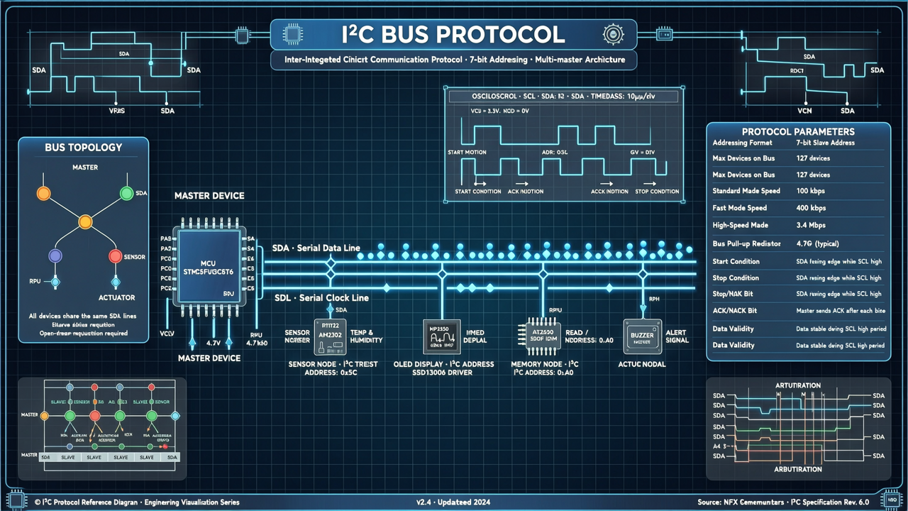
2.1 Physical Layer: SCL and SDA
The physical connection for I2C is remarkably simple:
- SCL (Serial Clock): the clock line, driven by the master device
- SDA (Serial Data): the data line, bidirectional
The key point: both lines use an open-drain structure, meaning external pull-up resistors are required for them to function. This is why both lines sit at a high level when I2C is idle — it’s not the chip actively outputting high; it’s the pull-up resistors pulling the lines up.
When a device needs to communicate, it pulls the line low. This design has an important benefit: multiple devices can share the same line without bus contention (wired-AND logic: if any device pulls low, the bus is low).
2.2 Communication Flow: START, STOP, ACK
A single I2C transaction consists of the following stages:
① START Condition
The master pulls SDA from high to low while SCL is high. This signals all slave devices: “Attention, I’m about to start communicating.”
② Address Transmission
After START, the master sends a 7-bit (or 10-bit) slave address plus a 1-bit read/write direction bit:
0= Write (master → slave)1= Read (slave → master)
③ Acknowledge (ACK/NACK)
After every 8 bits of data, the receiver must pull SDA low during the 9th clock cycle as an acknowledgement (ACK). If the receiver doesn’t pull low (keeps it high), that’s a NACK, meaning “I didn’t receive it” or “I don’t exist.”
④ Data Transfer
After ACK, data transfer begins. Each byte is 8 bits, MSB first. Every byte must be followed by an ACK.
⑤ STOP Condition
The master releases SDA from low to high while SCL is high. Communication ends and the bus is released.
2.3 7-Bit Address vs 10-Bit Address
7-bit addressing is the most common I2C mode, theoretically supporting 128 devices (2⁷ = 128). But the actual number of usable addresses is smaller because some are reserved (e.g., the general call address 0x00).
10-bit addressing expands the address space to 1024 devices, but it’s rarely used because:
- Most I2C devices only support 7-bit addressing
- The protocol is more complex, requiring two bytes just for the address
- Real-world projects rarely need more than 128 devices on a single bus
Common I2C Device Addresses:
| Device Type | Typical Address | Notes |
|---|---|---|
| BME280 Temp/Humidity | 0x76 or 0x77 | Depends on SDO pin |
| SSD1306 OLED | 0x3C or 0x3D | 128×64 commonly uses 0x3C |
| DS3231 RTC | 0x68 | Fixed address |
| MPU6050 Gyroscope | 0x68 or 0x69 | Depends on AD0 pin |
| EEPROM 24Cxx | 0x50–0x57 | Depends on A0/A1/A2 pins |
💡 Tip: If you’re unsure of a device’s address, use Arduino’s I2C Scanner to scan all devices on the bus. The code is in the hands-on section below.
3. I2C Speed Modes: From 100kHz to 3.4MHz
I2C isn’t a single speed — it has multiple speed grades. Choosing the wrong mode can cause communication failures or data errors.
3.1 Four Speed Modes
| Mode | Speed | Typical Use Cases |
|---|---|---|
| Standard-mode | 100 kbps | Most sensors, EEPROMs |
| Fast-mode | 400 kbps | OLED displays, high-speed ADCs |
| Fast-mode Plus | 1 Mbps | Newer MCU peripherals |
| High-speed mode | 3.4 Mbps | Special high-speed devices |
3.2 Practical Considerations for Speed Selection
Faster isn’t always better. Higher speeds demand better signal quality:
- Lower pull-up resistance (stronger drive capability)
- Shorter traces (reduce parasitic capacitance)
- Lower noise margin (more susceptible to interference)
Most sensors work well at 100kHz or 400kHz. Unless you have a specific high-speed requirement (e.g., driving a high-resolution OLED), Standard-mode is the safest choice.
Default speeds for ESP32 and Arduino:
- Arduino (ATmega328P): 100kHz by default
- ESP32: 100kHz by default, but hardware supports up to 1MHz
Boosting the speed is straightforward in code:
// Arduino
Wire.begin();
Wire.setClock(400000);  // Set to 400kHz Fast-mode

// ESP32
Wire.begin(SDA_PIN, SCL_PIN);
Wire.setClock(400000);  // Also supported
⚠️ Note: Before increasing speed, make sure all slave devices support that speed. If a 100kHz sensor is on a 400kHz bus, communication will fail.
⚠️ Note: Before increasing speed, make sure all slave devices support that speed. If a 100kHz sensor is on a 400kHz bus, communication will fail.
4. Pull-Up Resistor Calculation: Why You Need Them and How to Choose
This is the most overlooked — and most problematic — aspect of I2C.
4.1 Why Do You Need Pull-Up Resistors?
As mentioned earlier, I2C’s SCL and SDA lines are both open-drain. Open-drain means the transistor inside the chip can only pull the line low (to ground); it cannot actively drive a high level.
So where does the high level come from? From external pull-up resistors connected to VCC.
Without pull-up resistors, the I2C bus will never return to a high level, and communication will simply not work.
4.2 How to Calculate Pull-Up Resistor Values
The I2C specification provides formulas for the minimum and maximum pull-up resistor values:
Minimum value (to ensure VOL ≤ 0.4V):
Rpull_min = (VCC - VOL_max) / IOL_maxTypical values: VCC = 3.3V, VOL_max = 0.4V, IOL_max = 3mA → Rpull_min = (3.3 - 0.4) / 0.003 ≈ 967Ω
Maximum value (to ensure rise time requirements are met):
Rpull_max = tr / (0.8473 × Cb)Where tr is the maximum allowed rise time, and Cb is the bus capacitance.
For Standard-mode (tr = 1000ns, Cb = 400pF): → Rpull_max = 1000 / (0.8473 × 400) ≈ 2.95kΩ
For Fast-mode (tr = 300ns, Cb = 400pF): → Rpull_max = 300 / (0.8473 × 400) ≈ 885Ω
4.3 Practical Rule-of-Thumb Values
The theoretical calculations can get complex. In practice, engineers commonly use these values:
| VCC | Standard-mode (100kHz) | Fast-mode (400kHz) |
|---|---|---|
| 3.3V | 4.7kΩ | 2.2kΩ |
| 5.0V | 4.7kΩ | 2.2kΩ |
Some practical guidelines:
- More devices on the bus → lower pull-up resistance (because bus capacitance increases)
- Longer traces → lower pull-up resistance (same reason — capacitance)
- 4.7kΩ is a universal starting value — works in most scenarios
- If communication is unstable, try 2.2kΩ first, then 1kΩ if that doesn’t help
- Don’t use resistors that are too small (< 1kΩ) — this increases power consumption and may exceed the chip’s sink current capability
💡 Practical tip: Many sensor modules (e.g., GY-BME280, SSD1306 OLED) already have built-in pull-up resistors (typically 4.7kΩ). If you’re only connecting one module, you don’t need additional pull-ups. But when connecting multiple modules, the parallel combination of pull-up resistors effectively reduces the resistance, which may cause the low level to not be low enough — check and adjust accordingly.
5. Hands-On ①: Arduino Reading a BME280 Temperature/Humidity Sensor
5.1 Hardware Wiring
| Arduino Uno | BME280 |
|---|---|
| A4 (SDA) | SDA |
| A5 (SCL) | SCL |
| 3.3V | VCC |
| GND | GND |
⚠️ BME280 operates at 1.8V–3.6V. Do not connect 5V — it will destroy the chip.
5.2 Installing Libraries
In the Arduino IDE:
Tools → Manage Libraries → Search "Adafruit BME280" → Install- Also install the
Adafruit Unified Sensorlibrary (dependency)
5.3 Complete Code
#include <Wire.h>
#include <Adafruit_Sensor.h>
#include <Adafruit_BME280.h>

// BME280 address: 0x76 (default) or 0x77 (SDO pulled high)
#define BME280_ADDRESS 0x76

Adafruit_BME280 bme;

void setup() {
  Serial.begin(115200);
  Serial.println("=== I2C BME280 Hands-On ===");

  // Initialize I2C
  Wire.begin();
  // Wire.setClock(100000);  // Standard-mode 100kHz

  // Initialize BME280
  if (!bme.begin(BME280_ADDRESS)) {
    Serial.println("Error: BME280 sensor not found. Check wiring and address.");
    while (1) delay(100);
  }
  Serial.println("BME280 initialized successfully!");
  Serial.println();
}

void loop() {
  // Read temperature, humidity, and pressure
  float temp = bme.readTemperature();   // °C
  float humidity = bme.readHumidity();  // %
  float pressure = bme.readPressure() / 100.0F; // hPa

  // Output to serial
  Serial.print("Temp: "); Serial.print(temp, 1); Serial.println(" °C");
  Serial.print("Humi: "); Serial.print(humidity, 1); Serial.println(" %");
  Serial.print("Pres: "); Serial.print(pressure, 1); Serial.println(" hPa");
  Serial.println("---");

  delay(2000);  // Read every 2 seconds
}
5.4 I2C Device Scanner Code
If you’re not sure whether your BME280’s address is 0x76 or 0x77, use this code to scan:
#include <Wire.h>

void setup() {
  Serial.begin(115200);
  Wire.begin();

  Serial.println("I2C Device Scanner:");
  byte count = 0;

  for (byte address = 1; address < 127; address++) {
    Wire.beginTransmission(address);
    byte error = Wire.endTransmission();

    if (error == 0) {
      Serial.print("Device found at address: 0x");
      if (address < 16) Serial.print("0");
      Serial.println(address, HEX);
      count++;
    }
  }

  if (count == 0) {
    Serial.println("No I2C devices found.");
  } else {
    Serial.print("Total devices found: ");
    Serial.print(count);
    Serial.println();
  }
}

void loop() {
  // Scan only once, no loop needed
  delay(100000);
}
This scanner is a must-have tool in every I2C developer’s toolbox. When a device won’t connect or you’ve got the wrong address, just run it and you’ll know immediately.
This scanner is a must-have tool in every I2C developer’s toolbox. When a device won’t connect or you’ve got the wrong address, just run it and you’ll know immediately.
6. Hands-On ②: ESP32 Multi-Device I2C Setup (OLED + BME280 + RTC)
6.1 Scenario Overview
In this section, we’ll tackle multi-device mounting — a very common requirement in real projects.
We’ll connect three devices simultaneously:
- SSD1306 OLED display (0x3C)
- BME280 temperature/humidity sensor (0x76)
- DS3231 RTC clock module (0x68)
6.2 Hardware Wiring
| ESP32 GPIO | Device | Description |
|---|---|---|
| GPIO 21 | SDA | I2C data line |
| GPIO 22 | SCL | I2C clock line |
| 3.3V | VCC | All devices use 3.3V |
| GND | GND | Common ground |
⚠️ ESP32 I2C pins are configurable, but the defaults are GPIO 21 (SDA) and GPIO 22 (SCL). This example uses the default pins.
6.3 Installing Libraries
Install these in the Arduino IDE Library Manager:
Adafruit SSD1306(OLED driver)Adafruit GFX Library(graphics library, dependency for SSD1306)Adafruit BME280 LibraryRTClib(DS3231 driver)
6.4 Complete Code
#include <Wire.h>
#include <Adafruit_Sensor.h>
#include <Adafruit_BME280.h>
#include <Adafruit_GFX.h>
#include <Adafruit_SSD1306.h>
#include <RTClib.h>

// ============== Pin Definitions ==============
#define SCREEN_WIDTH 128
#define SCREEN_HEIGHT 64
#define OLED_RESET    -1  // No Reset pin used

// I2C address definitions
#define OLED_ADDRESS   0x3C
#define BME280_ADDRESS 0x76
#define RTC_ADDRESS    0x68

// ============== Initialize Objects ==============
Adafruit_SSD1306 display(SCREEN_WIDTH, SCREEN_HEIGHT, &Wire, OLED_RESET);
Adafruit_BME280 bme;
RTC_DS3231 rtc;

// ============== Setup ==============
void setup() {
  Serial.begin(115200);
  delay(1000);

  // Initialize I2C
  Wire.begin(21, 22);  // SDA=21, SCL=22
  Wire.setClock(400000);  // Fast-mode 400kHz

  // Initialize OLED
  if (!display.begin(SSD1306_SWITCHCAPVCC, OLED_ADDRESS)) {
    Serial.println("OLED initialization failed");
  } else {
    display.clearDisplay();
    display.setTextSize(1);
    display.setTextColor(SSD1306_WHITE);
    Serial.println("OLED initialized successfully");
  }

  // Initialize BME280
  if (!bme.begin(BME280_ADDRESS)) {
    Serial.println("BME280 initialization failed");
  } else {
    Serial.println("BME280 initialized successfully");
  }

  // Initialize RTC
  if (!rtc.begin()) {
    Serial.println("RTC initialization failed");
  } else {
    // Set time on first power-up (comment out to avoid resetting every time)
    // rtc.adjust(DateTime(F(__DATE__), F(__TIME__)));
    Serial.println("RTC initialized successfully");
  }

  Serial.println("=== System initialization complete ===");
  Serial.println();
}

// ============== Main Loop ==============
void loop() {
  // Get current time
  DateTime now = rtc.now();

  // Get temperature, humidity, and pressure
  float temp = bme.readTemperature();
  float humidity = bme.readHumidity();
  float pressure = bme.readPressure() / 100.0F;

  // Serial output
  Serial.printf("%04d-%02d-%02d %02d:%02d:%02d\n",
    now.year(), now.month(), now.day(),
    now.hour(), now.minute(), now.second());
  Serial.printf("Temp: %.1f°C | Humi: %.1f%% | Pres: %.0fhPa\n",
    temp, humidity, pressure);
  Serial.println("---");

  // OLED display
  display.clearDisplay();
  display.setCursor(0, 0);
  display.setTextSize(1);
  display.printf("%02d:%02d:%02d\n",
    now.hour(), now.minute(), now.second());

  display.setTextSize(1);
  display.print("Temp: ");
  display.setTextSize(2);
  display.printf("%.1fC\n", temp);

  display.setTextSize(1);
  display.print("Humi: ");
  display.setTextSize(2);
  display.printf("%.0f%%\n", humidity);

  display.setTextSize(1);
  display.print("Pres: ");
  display.setTextSize(2);
  display.printf("%.0fhPa", pressure);

  display.display();

  delay(2000);
}
6.5 Multi-Device Considerations
- No address conflicts: The three devices all have different addresses (0x3C, 0x68, 0x76), so they can coexist
- Pull-up resistors: If each device works individually but fails when combined, check the pull-up resistors first
- Bus capacitance: More devices = more bus capacitance; you may need to lower the pull-up resistance (from 4.7kΩ to 2.2kΩ)
- Software I2C: ESP32’s hardware I2C sometimes has compatibility issues with certain OLEDs. If you encounter display problems, try a software I2C library (SoftwareWire)
💡 Debugging tip: Test each device individually first. Once they all work on their own, then combine them. Use the I2C Scanner to verify addresses when troubleshooting.
💡 Debugging tip: Test each device individually first. Once they all work on their own, then combine them. Use the I2C Scanner to verify addresses when troubleshooting.
7. What to Do About I2C Address Conflicts? Solutions for Multiple Devices with the Same Address
Address conflicts are the most common problem in multi-device I2C setups. When two devices share the same address, the I2C bus doesn’t know which one to talk to.
7.1 Why Do Address Conflicts Occur?
Many I2C chips have fixed default addresses. For example:
- DS3231 RTC: 0x68 (fixed)
- MPU6050 gyroscope: default 0x68
If you connect both a DS3231 and an MPU6050 on the same bus, address 0x68 conflicts and neither device can communicate properly.
7.2 Solutions
Solution 1: Use Hardware Address Pins
Many chips provide address configuration pins. For example:
- BME280: SDO pin to GND = 0x76, to VCC = 0x77
- MPU6050: AD0 pin to GND = 0x68, to VCC = 0x69
- EEPROM 24Cxx: A0/A1/A2 pin combinations, 0x50–0x57
When buying modules, check if they have address configuration pins — this is the simplest fix.
Solution 2: Use Software I2C (Multiple I2C Buses)
If hardware addresses can’t be changed, you can use the ESP32’s multiple I2C buses:
// ESP32 has two hardware I2C buses
// I2C Bus 0: OLED + RTC
Wire.begin(21, 22);  // SDA=21, SCL=22

// I2C Bus 1: MPU6050 (using a different set of pins)
Wire1.begin(25, 26);  // SDA=25, SCL=26
The ESP32 supports two hardware I2C buses — one of its advantages over the Arduino Uno.
Solution 3: I2C Multiplexer (TCA9548A)
If you have too many devices, use a TCA9548A (8-channel I2C multiplexer). It lets you switch between 8 independent sub-buses on the same I2C bus, with each sub-bus able to have devices with identical addresses.
#include <Wire.h>
#include <TCA9548A.h>

TCA9548A mux;  // Address 0x70

void setup() {
  Wire.begin();
  mux.begin();
}

void loop() {
  // Switch to channel 0, read sensor A
  mux.selectChannel(0);
  readSensorA();

  // Switch to channel 1, read sensor B (can have the same address as A)
  mux.selectChannel(1);
  readSensorB();
}
💡 Real-world experience: The TCA9548A is common in industrial IoT projects. When your monitoring node needs 10+ sensors of the same model, a multiplexer is almost the only option.
💡 Real-world experience: The TCA9548A is common in industrial IoT projects. When your monitoring node needs 10+ sensors of the same model, a multiplexer is almost the only option.
8. I2C Troubleshooting: Logic Analyzer Captures and Oscilloscope Waveforms
When I2C communication fails, the worst thing you can do is guess. Use tools when you have them; when you don’t, systematically eliminate possibilities.
8.1 Basic Troubleshooting Checklist
When communication doesn’t work, check in this order:
- Is the wiring correct? SDA to SDA, SCL to SCL — don’t swap them
- Are there pull-up resistors? No pull-ups = no communication
- Is the voltage compatible? 3.3V devices connected to a 5V MCU need level shifting
- Is the address correct? Use the I2C Scanner to confirm
- Is the device powered? Measure the VCC pin voltage with a multimeter
- Are the wires too long? I2C recommends < 30cm; longer traces degrade signal quality
8.2 Logic Analyzer Capture
A logic analyzer is the go-to tool for debugging I2C issues. An affordable 24MHz 8-channel logic analyzer costs just a few dollars and works with PulseView (open-source) or Saleae Logic software.
Wiring:
- Channel 0 → SCL
- Channel 1 → SDA
- GND → GND
PulseView settings:
- Sample rate: 1MHz or higher
- Decoder: select “I²C”
- Configure SCL and SDA channel assignments
Useful information you can see:
- Whether START/STOP conditions are correct
- Address byte and read/write direction
- Data content and ACK/NACK
- Whether the clock frequency matches expectations
Common problem waveform signatures:
- All NACKs: Wrong address or device not powered
- Garbled data: Clock frequency mismatch or signal interference
- No START: Code didn’t properly initialize Wire
- Slow rising edges: Pull-up resistors too large or bus capacitance too high
8.3 Oscilloscope Waveform Analysis
If you have an oscilloscope, you can view the analog waveforms directly — more intuitive than a logic analyzer:
- Rise time: Standard-mode should be < 1000ns, Fast-mode < 300ns
- Low-level voltage: Should be < 0.4V; too high means pull-up resistors aren’t strong enough
- High-level voltage: Should be close to VCC; too low suggests leakage or excessive loading
- Glitches/noise: Indicates interference — check grounding and trace routing
💡 From experience: 80% of I2C problems are wiring or pull-up resistor issues. Start with a multimeter to check voltages and a Scanner to verify addresses before reaching for the logic analyzer. Don’t jump straight to waveform capture — it’s a waste of time.
💡 From experience: 80% of I2C problems are wiring or pull-up resistor issues. Start with a multimeter to check voltages and a Scanner to verify addresses before reaching for the logic analyzer. Don’t jump straight to waveform capture — it’s a waste of time.
9. I2C vs SPI vs UART: When to Use Which?
These are the three most common serial communication protocols in embedded development, each with its own strengths and weaknesses. Choosing the wrong one won’t make things impossible, but it’ll make your life harder.
9.1 Comparison Overview
| Feature | I2C | SPI | UART |
|---|---|---|---|
| Wires | 2 (SDA + SCL) | 4 (MOSI + MISO + SCK + CS) | 2 (TX + RX) |
| Speed | 100kHz – 3.4MHz | 10MHz – 80MHz+ | 9600 – 115200bps (common) |
| Multi-device | ✅ Multiple on one bus | ⚠️ Each device needs its own CS line | ❌ Point-to-point |
| Full duplex | ❌ Half duplex | ✅ Full duplex | ✅ Full duplex |
| Master/slave | Multi-master, multi-slave | One master, multiple slaves | Point-to-point |
| Distance | Short (< 1m) | Very short (< 30cm) | Longer (up to several meters) |
| Complexity | Medium | Simple | Simplest |
9.2 When to Choose I2C?
- Pin-constrained designs: Only 2 pins to spare — I2C is the only choice
- Multi-device setups: Multiple sensors on one bus without individual wiring for each
- Low speed requirements: Sensor data acquisition, OLED displays, EEPROM read/write
- Board-to-board communication: Inter-chip communication on the same PCB
9.3 When to Choose SPI?
- High-speed transfers: SD cards, TFT displays, high-speed ADCs
- Full-duplex needs: Simultaneous send and receive
- Few devices: Each additional SPI device adds a CS line — too many devices means a wiring mess
9.4 When to Choose UART?
- Cross-board/cross-module communication: e.g., MCU to WiFi module (ESP8266/ESP32)
- Debug output: Serial.print is UART
- Long-distance communication: RS485 is essentially UART’s long-distance variant
- No clock line needed: Asynchronous — just agree on the baud rate
9.5 Combining Protocols in Real Projects
A typical IoT project often uses all three protocols simultaneously:
MCU (ESP32)
├── I2C → BME280 sensor + OLED display + RTC clock
├── SPI → SD card storage + LoRa module
└── UART → GPS module + 4G Cat.1 module + debug output
No single protocol is a silver bullet. The key is understanding their boundaries and using the right protocol for the right scenario.
💡 Coming up: In a future article, we’ll do a deep-dive comparison of SPI vs I2C vs UART, from protocol details to real-world performance benchmarks, to help you fully understand these three workhorses.
10. Summary
The I2C bus looks simple — it’s just two wires, right? — but engineers who truly use it well understand its quirks.
Let’s recap today’s key takeaways:
- Protocol basics: START → Address + R/W → Data transfer (ACK per byte) → STOP — this is the skeleton of I2C
- Open-drain structure: Pull-up resistors are mandatory; 4.7kΩ is the starting value, drop to 2.2kΩ if unstable
- Speed matching: Confirm all slave devices support the speed before increasing it, or communication will fail
- Address conflicts: Use hardware pins to change addresses first; if that’s not possible, use a TCA9548A multiplexer
- Debugging tools: Start with a multimeter and Scanner, then move to a logic analyzer — don’t start by guessing
- Protocol selection: I2C isn’t a cure-all — use SPI for high speed, UART for long distance, and combine as needed
I2C is a fundamental skill in embedded development. Use it well, and your projects will be more stable, more pin-efficient, and more elegant.
Got questions? Drop a comment. What I2C pitfalls have you run into? How did you solve them? Let’s discuss.
Recommended Reading: