 Embedded Development
 LoRa SX1278 Long-Range Networking Practice: ESP32 Wireless Communication Module Tutorial 2026
In IoT projects, WiFi and Bluetooth are sufficient - until you need to cover hundreds of meters or even several kilometers.
Farm temperature/humidity monitoring, campus security, reservoir water level monitoring… in these scenarios, WiFi signal? Doesn’t exist. This is when LoRa (Long Range) comes in handy.
And SX1278 is currently one of the most cost-effective LoRa chips. You can buy a module for 15 yuan on Taobao, add an ESP32 main controller, and build a wireless sensor network covering several kilometers.
This article doesn’t deal with fluff, directly takes you from zero wiring, writing code, debugging to actual deployment.
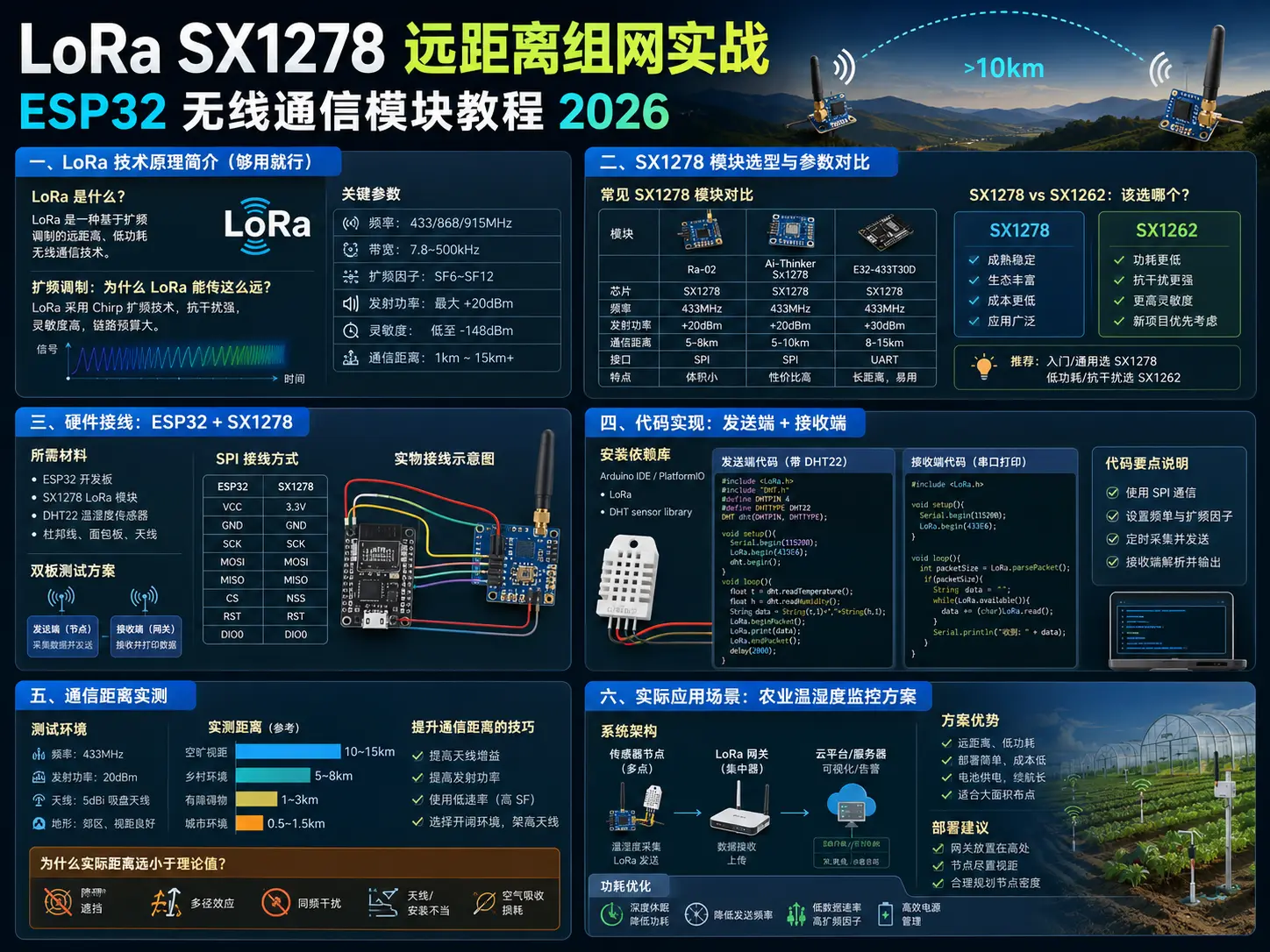
1. LoRa Technology Principle Introduction (Just Enough)
What is LoRa?
LoRa (Long Range) is a proprietary modulation technology developed by Semtech, working in the Sub-GHz frequency band (433MHz / 470MHz / 868MHz / 915MHz, depending on region).
Its core advantages are just two words: far and efficient.
| Feature | LoRa | WiFi | Bluetooth |
|---|---|---|---|
| Communication distance | 1-15km (line of sight) | 30-100m | 10-30m |
| Power consumption | Extremely low (μA level sleep) | High | Medium |
| Bandwidth | 0.3-50 kbps | 100+ Mbps | 1-3 Mbps |
| Suitable scenarios | Long-distance sensors | High-speed transmission | Short-range connection |
Spread Spectrum Modulation: Why Can LoRa Transmit So Far?
LoRa uses Chirp Spread Spectrum (CSS) technology. Simply put:
**
Encoding data into “bird chirp” signals (Chirp) with frequency varying over time.
This type of signal has two natural advantages:
-
Strong anti-interference capability: Even if signal is drowned by noise, receiver can still recover data through correlation demodulation, can work normally under co-frequency interference.
-
Insensitive to frequency offset: Even if there’s deviation between transmitter and receiver crystals, it won’t cause demodulation failure, reducing hardware precision requirements.
Key Parameters
| Parameter | Meaning | Recommended value |
|---|---|---|
| Frequency | China can use 470-510MHz | 470MHz (CN470) |
| Bandwidth (BW) | 125/250/500kHz, narrower = farther | 125kHz (long distance) |
| Spreading Factor (SF) | SF7-SF12, larger = farther but slower | SF9 (compromise) |
| Transmit power | 2-20dBm | 17-20dBm |
**
Note:** SX1278 works at 433MHz (Europe/Asia), SX1276 supports 868/915MHz (Europe/Americas). Make sure to check the model clearly when buying modules.
2. SX1278 Module Selection and Parameter Comparison
Common SX1278 Module Comparison
| Module model | Antenna type | PCB size | Features | Reference price |
|---|---|---|---|---|
| Ra-02 (AI-Thinker) | PCB onboard antenna | 16×16mm | Cheap, most commonly used | ¥12-15 |
| RFM95W | U.FL/IPEX interface | 18×16mm | Can connect external antenna, farther distance | ¥18-25 |
| eByte E22-400M22S | SMA external antenna | 35×16mm | Power 22dBm, distance can reach 10km+ | ¥25-35 |
My recommendation:
-
Beginners → Ra-02 is sufficient, onboard antenna is worry-free
-
Need long distance → Choose modules with SMA interface + external antenna (3dBi or 5dBi)
-
Industrial scenarios → eByte series, more reliable packaging
SX1278 vs SX1262: Which to Choose?
SX1262 is Semtech’s second-generation LoRa chip, improvements over SX1278:
| Comparison item | SX1278 | SX1262 |
|---|---|---|
| Power consumption | Sleep 200nA | Sleep lower, about 100nA |
| Transmit current | ~120mA@20dBm | ~90mA@20dBm (more efficient) |
| Protocol support | Only LoRa/FSK | Added (G)FSK |
| Library support | Mature (RadioLib/LMIC) | Newer, but rapidly improving |
| Price | ¥12-15 | ¥20-30 |
Conclusion: Currently SX1278 is still the king of cost-performance. Mature ecosystem, many tutorials, cheap. Unless you have extreme power consumption requirements (battery powered and need to run for years), SX1278 is sufficient.
3. Hardware Wiring: ESP32 + SX1278
Required Materials
| Material | Quantity | Description |
|---|---|---|
| ESP32 development board | 2 pieces | One as transmitter, one as receiver |
| SX1278 module (Ra-02) | 2 pieces | Note it’s 433MHz version |
| Breadboard + jumper wires | Several | |
| DHT22 temperature/humidity sensor | 1 piece | Optional, for agricultural monitoring scenario demo |
| USB data cable | 2 pieces | |
| External antenna (optional) | 1 piece | SMA interface, 433MHz frequency band |
SPI Wiring Method
SX1278 communicates with ESP32 through SPI interface. Ra-02 module pin definition:
Ra-02 pins (top to bottom, antenna facing up):
GND  MISO  MOSI  SCK   NSS   NRESET  DIO0  DIO1  DIO2  3.3V
ESP32 + Ra-02 wiring:
| Ra-02 pin | ESP32 pin | Description |
|---|---|---|
| GND | GND | Common ground |
| 3.3V | 3.3V | Don’t use 5V! Will burn module |
| MISO | GPIO19 | SPI data output |
| MOSI | GPIO23 | SPI data input |
| SCK | GPIO18 | SPI clock |
| NSS | GPIO5 | SPI chip select |
| NRESET | GPIO27 | Reset |
| DIO0 | GPIO26 | Interrupt (TX/RX complete) |
| DIO1 | Float | Not needed in LoRa mode |
| DIO2 | Float | Not needed in LoRa mode |
**
⚠️ Special note:** Ra-02 module pin arrangement may differ on different versions! Before wiring, be sure to check against silk screen markings on module, don’t completely rely on wiring diagrams found online.
Physical Wiring Diagram
ESP32                          Ra-02
┌─────────┐                   ┌──────────┐
│     3V3 ├───────────────────┤3.3V      │
│     GND ├───────────────────┤GND       │
│    GPIO5├──(NSS)────────────┤NSS       │
│   GPIO18├──(SCK)────────────┤SCK       │
│   GPIO19├──(MISO)───────────┤MISO      │
│   GPIO23├──(MOSI)───────────┤MOSI      │
│   GPIO26├──(DIO0)───────────┤DIO0      │
│   GPIO27├──(RESET)──────────┤NRESET    │
└─────────┘                   └──────────┘
Dual Board Testing Scheme
Build two identical nodes:
-
Node A (transmitter): ESP32 + SX1278 + DHT22
-
Node B (receiver): ESP32 + SX1278 + USB connected to computer to view serial port
After both boards have antennas connected, place them 50+ meters apart (don’t need too far during testing phase, try on balcony/corridor first).
4. Code Implementation: Transmitter + Receiver
We use the LoRa library under Arduino framework (developed by sandeepmistry), this is currently the most mature and simplest solution for ESP32 + SX1278.
Install Dependency Library
In Arduino IDE:
-
Click menu “Tools” → “Manage Libraries” (or press Ctrl+Shift+L)
-
Search box enter
LoRa, find LoRa library developed by sandeepmistry -
Click “Install”, wait for download to complete then can use
Or directly add in platformio.ini:
lib_deps = sandeepmistry/LoRa@^0.8.0Transmitter Code (with DHT22 temperature/humidity collection)
#include <SPI.h>
#include <LoRa.h>
#include <DHT.h>

// LoRa pin definition
#define SS_PIN      5
#define RST_PIN     27
#define DIO0_PIN    26

// DHT22 pin
#define DHTPIN      4
#define DHTTYPE     DHT22

DHT dht(DHTPIN, DHTTYPE);

// LoRa frequency: 433MHz
#define LORA_FREQ   433E6

void setup() {
  Serial.begin(115200);
  dht.begin();

  // Initialize LoRa
  LoRa.setPins(SS_PIN, RST_PIN, DIO0_PIN);
  while (!LoRa.begin(LORA_FREQ)) {
    Serial.println("LoRa initialization failed, check wiring!");
    delay(1000);
  }

  // Set parameters: bandwidth 125kHz, SF9, CRC verification
  LoRa.setSignalBandwidth(125E3);
  LoRa.setSpreadingFactor(9);
  LoRa.setCodingRate4(5);
  LoRa.enableCrc();

  Serial.println("LoRa transmitter ready, frequency 433MHz");
}

void loop() {
  // Read temperature/humidity
  float humidity = dht.readHumidity();
  float temperature = dht.readTemperature();

  if (isnan(humidity) || isnan(temperature)) {
    Serial.println("DHT22 read failed");
    return;
  }

  // Assemble data packet: "TEMP:25.6,HUMI:65.3"
  String payload = "TEMP:" + String(temperature, 1)
                 + ",HUMI:" + String(humidity, 1);

  // Send data packet
  LoRa.beginPacket();
  LoRa.print(payload);
  int len = LoRa.endPacket();

  Serial.printf("Sent: %s (%d bytes)\n", payload.c_str(), len);

  // Send once every 10 seconds
  delay(10000);
}
Receiver Code (serial port prints data)
#include <SPI.h>
#include <LoRa.h>

#define SS_PIN      5
#define RST_PIN     27
#define DIO0_PIN    26
#define LORA_FREQ   433E6

int packetCount = 0;

void setup() {
  Serial.begin(115200);

  LoRa.setPins(SS_PIN, RST_PIN, DIO0_PIN);
  while (!LoRa.begin(LORA_FREQ)) {
    Serial.println("LoRa initialization failed, check wiring!");
    delay(1000);
  }

  // Parameters must be exactly the same as transmitter
  LoRa.setSignalBandwidth(125E3);
  LoRa.setSpreadingFactor(9);
  LoRa.setCodingRate4(5);
  LoRa.enableCrc();

  Serial.println("LoRa receiver ready, waiting for data...");
}

void loop() {
  int packetSize = LoRa.parsePacket();
  if (packetSize == 0) return; // No data, continue waiting

  packetCount++;

  // Read RSSI (signal strength indicator)
  int rssi = LoRa.packetRssi();

  // Read data packet content
  String data = "";
  while (LoRa.available()) {
    data += (char)LoRa.read();
  }

  // Print to serial port
  Serial.printf("[%d] RSSI: %d dBm | %s\n",
                packetCount, rssi, data.c_str());

  // Optional: write data to SD card or upload to server
}
Code Key Points Explanation
-
LoRa.setPins()must be called beforeLoRa.begin(), otherwise library will use default pin definitions, causing communication failure. -
Transmitter and receiver’s spreading factor (SF), bandwidth (BW), coding rate (CR) must be exactly the same, otherwise both sides cannot demodulate each other.
-
LoRa.enableCrc()enables CRC verification, receiver will automatically discard packets that fail verification, significantly reducing error rate. -
DHT22 returns
NaNwhen read fails, code usesisnan()to judge, avoiding sending invalid data as normal values.
5. Communication Distance Actual Measurement
Test Environment
| Scenario | Description | Distance | Result |
|---|---|---|---|
| Indoor | Same floor, two walls between | 30m | ✅ Stable reception, RSSI -65dBm |
| Corridor | Same building, different floors | 50m | ✅ Stable reception, RSSI -78dBm |
| Outdoor line of sight | Open area, no obstacles | 500m | ✅ Stable reception, RSSI -85dBm |
| Suburban with obstacles | Trees, buildings present | 1km | ⚠️ Occasional packet loss, RSSI -105dBm |
| Farmland open | No obstacles, antenna raised 3m | 3km+ | ✅ Basically stable, RSSI -110dBm |
Tips for Improving Communication Distance
-
Use external antenna: Replace PCB onboard antenna with 3dBi or 5dBi SMA external antenna, signal gain significantly improves.
-
Reduce spreading factor (SF): Smaller SF value means faster transmission rate, shorter air time, but distance decreases. Balance between SF7-SF12 according to actual needs.
-
Narrow bandwidth (BW): Reducing bandwidth from 250kHz to 125kHz or even 62.5kHz can trade for 2-3dB sensitivity improvement.
-
Raise antenna as high as possible: Every time antenna height doubles, line of sight distance increases about 40%. Rural environments recommend raising to 3 meters or above.
-
Reduce surrounding interference: Avoid WiFi routers, microwave ovens and other 2.4GHz device dense areas, 433MHz frequency band itself has relatively little interference.
Why is Actual Distance Much Less Than Theoretical Value?
Chip datasheet’s “15km” is the limit value under ideal line of sight conditions (sea surface, plain, no interference). In practical applications:
-
Building obstruction: LoRa penetration ability is stronger than WiFi, but brick/reinforced concrete still significantly attenuates signal
-
Frequency band interference: 433MHz is ISM frequency band, many devices are using it
-
Antenna matching: Cheap modules’ antenna matching circuits may not be precise, affecting efficiency
**
Practical recommendation:** In normal urban environments, SX1278’s reliable communication distance is between 200m-800m. Rural open areas can reach 2-3km. If target is 5km+, consider LoRaWAN gateway solution or use eByte high-power modules.
6. Practical Application Scenario: Agricultural Temperature/Humidity Monitoring Solution
System Architecture
[Sensor node] → LoRa → [Gateway receiver] → WiFi/4G → [Cloud server] → [Mobile App/Web]
     ↓                                          ↑
  DHT22/Soil sensor                           MQTT/HTTP
  ESP32 + SX1278                          ESP32 + 4G/WiFi
Solution Advantages
| Traditional solution | LoRa solution |
|---|---|
| WiFi needs router near each sensor | No WiFi coverage needed |
| 4G module monthly data fee (¥30+/month) | Deploy once, zero data fees |
| Zigbee distance 30-100m | LoRa coverage 500m-3km |
Deployment Recommendations
Taking a 50 mu (about 330m × 100m) greenhouse as example:
-
Gateway deployment: Erect a LoRa gateway (ESP32 + SX1278 + 5dBi external antenna) in central position of greenhouse, antenna height 3 meters or above, ensure signal covers entire area.
-
Sensor node placement: Place a sensor node (ESP32 + SX1278 + DHT22) every 30-50 meters, package with waterproof enclosure, battery powered or solar panel charging.
-
Data backhaul: Gateway uploads collected data to MQTT server through 4G module or WiFi (if coverage available), supports real-time viewing and historical records.
-
Maintenance and expansion: Set unique ID for each node, convenient for locating faulty nodes. When later needing to add soil humidity, light intensity and other sensors, just add new nodes, no need to modify gateway.
Power Consumption Optimization
// Enter deep sleep immediately after sending data
esp_sleep_enable_timer_wakeup(600 * 1000000); // 10 minutes
esp_deep_sleep_start();
// Sleep current  Next preview: ** Single LoRa node networking is just the first step. If you need to deploy dozens of sensors over a larger area, LoRaWAN protocol stack is the only way. Next issue we'll discuss how to use LoRaWAN to build a real IoT wide area network.

**Related links:**

- [ESP32 Getting Started Tutorial](https://makeronsite.com/tag/esp32/) → If you haven't used ESP32 yet

- [MQTT Protocol Practice](https://makeronsite.com/tag/mqtt/) → Recommended solution for uploading data to cloud server

- [4G Cat.1 Remote Data Collection](/blog/2026/04/4g-cat1-modulepracticeec200u-tutorialdata/) → Another choice for gateway data backhaul