 Embedded Development
 Complete Guide to Motor Control: Stepper/Servo/DC Motors + Closed-Loop Control in Practice
Introduction
Motor control is one of the most fundamental and important skills in embedded development. Whether you’re building a CNC engraver, robot joints, a smart car, or a solar power system, precise motor control is essential.
This guide is built around 5 hands-on projects, covering stepper motors (A4988), servos (SG90/MG996), DC motors (L298N PWM), encoder-based closed-loop PID control, and solar charge controllers (PWM vs MPPT) — consolidating scattered knowledge into a single comprehensive reference.
1. Stepper Motor Precision Control: A4988 Driver Deep Dive
1.1 Why Choose a Stepper Motor?
Stepper motors allow precise angular control without the need for an encoder, enabling open-loop position control. A NEMA 17 (42mm) stepper motor paired with an A4988 driver is the core solution for CNC engravers, 3D printers, and robot gimbals.
1.2 Bill of Materials
| Item | Model | Price | Notes |
|---|---|---|---|
| Stepper Motor | NEMA 17 (42mm) | ¥25-35 | 1.8° step angle, 1.5A |
| Driver | A4988 | ¥8-12 | Max 2A, supports microstepping |
| Dev Board | Arduino Uno | ¥25 | Or any compatible board |
| Potentiometer | 10kΩ | ¥2 | Adjust motor current |
| Capacitor | 100μF | ¥1 | Power supply filtering |
| Power Supply | 12V 2A | ¥30 | Motor power |
Total cost: approximately ¥100
1.3 A4988 Key Pins
+-----+
        VMOT ──────┤1   16│────── GND
         GND ──────┤2   15│────── 1B
          VDD ──────┤3   14│────── 1A
          2B ───────┤4   13│────── 2A
          2A ───────┤5   12│────── GND
        MS1 ────────┤6   11│────── VDD
        MS2 ────────┤7   10│────── STEP
        MS3 ────────┤8    9│────── DIR
+-----+- VMOT/GND: Motor power (8-35V), a 100μF decoupling capacitor is required
- VDD/GND: Logic power (3-5.5V), connect to Arduino 5V
- 1A/1B/2A/2B: Motor coil outputs
- STEP: Pulse signal — each pulse advances one step
- DIR: Direction control — HIGH for forward, LOW for reverse
- MS1/MS2/MS3: Microstepping configuration pins
1.4 Microstepping Configuration Table
| MS1 | MS2 | MS3 | Microstep Mode | Steps per Revolution |
|---|---|---|---|---|
| 0 | 0 | 0 | Full step | 200 |
| 1 | 0 | 0 | 1/2 step | 400 |
| 0 | 1 | 0 | 1/4 step | 800 |
| 1 | 1 | 0 | 1/8 step | 1600 |
| 1 | 1 | 1 | 1/16 step | 3200 |
1/16 microstepping is recommended for smoother operation and lower noise.
1.5 Current Adjustment (Important!)
The A4988 sets motor current via the reference voltage Vref using the formula: Vref = Current × 0.8
For a 1.5A NEMA 17: Vref = 1.5 × 0.8 = 1.2V
Adjustment procedure:
- Disconnect motor power; prepare a multimeter (set to DC voltage)
- Power the A4988 (connect VDD only, not VMOT) to avoid motor movement
- Use a screwdriver to slowly turn the potentiometer on the A4988
- Measure the voltage at the potentiometer wiper relative to GND until the reading is close to 1.2V
1.6 Arduino Control Code
Basic: AccelStepper Library (Recommended)
#include <AccelStepper.h>

// Define stepper pins
#define STEP_PIN 9
#define DIR_PIN 8

// Create stepper object
AccelStepper stepper(AccelStepper::DRIVER, STEP_PIN, DIR_PIN);

void setup() {
  Serial.begin(9600);
  stepper.setMaxSpeed(1000);        // Max speed (steps/sec)
  stepper.setAcceleration(500);     // Acceleration (steps/sec²)
  stepper.moveTo(3200);             // One full revolution (@ 1/16 microstep)
  Serial.println("Motor starting");
}

void loop() {
  if (stepper.distanceToGo() == 0) {
    stepper.moveTo(-stepper.currentPosition());  // Reverse
    Serial.print("Current position: ");
    Serial.println(stepper.currentPosition());
  }
  stepper.run();
}
Install library: Arduino IDE → Tools → Manage Libraries → Search “AccelStepper” → Install
Advanced: Multi-Axis Synchronized Control (CNC 3-Axis)
#include <AccelStepper.h>

AccelStepper xAxis(AccelStepper::DRIVER, 2, 3);
AccelStepper yAxis(AccelStepper::DRIVER, 4, 5);
AccelStepper zAxis(AccelStepper::DRIVER, 6, 7);

void setup() {
  xAxis.setMaxSpeed(1000);
  yAxis.setMaxSpeed(1000);
  zAxis.setMaxSpeed(1000);
}

void loop() {
  xAxis.moveTo(1000);
  yAxis.moveTo(500);
  zAxis.moveTo(200);
  xAxis.run();
  yAxis.run();
  zAxis.run();
}
1.7 Speed Calculation
RPM = (Pulse Frequency × 60) / Steps per RevolutionFor example, at 1/16 microstepping with 1000 pulses per second: RPM = (1000 × 60) / 3200 = 18.75 RPM
Note: The A4988’s maximum pulse frequency is approximately 200kHz, but in practice it’s recommended to stay below 50kHz — torque drops at higher speeds.
1.8 Common Troubleshooting
Motor hums but doesn’t turn:
- Check that coil wiring is correct — use a multimeter in continuity mode to identify coil pairs
- Increase the Vref current setting (but don’t exceed the motor’s rated current)
- Try turning the motor shaft by hand to check for mechanical binding
Driver overheating:
- Check if Vref is set too high — reduce to the motor’s rated current
- Add a heatsink (aluminum heatsinks work well)
- Check ventilation — avoid enclosed spaces
- Consider upgrading to a DRV8825 or TMC2208 (higher efficiency)
Motor jitters or moves erratically:
- Switch to a higher microstepping mode (1/16 or 1/32)
- Avoid resonance speed ranges (typically in the low-to-medium speed range)
- Check that all connections are secure — poor dupont wire contact is a common cause
Missed steps at high speed:
- Reduce acceleration to give the motor more response time
- Increase current within the rated range
- Check that the power supply is adequate (voltage sag reduces torque)
Arduino resets:
- Use separate power supplies for the motor and Arduino — share only ground
- Add a 100μF electrolytic capacitor across VMOT
- Verify all ground connections are solid
- Use optocouplers to isolate STEP/DIR signals if necessary
1.9 Project Applications
Once you’ve mastered stepper motor control, you can build:
- DIY mini CNC engraver (3-axis coordinated motion)
- 3D printer (with hotend and extruder)
- XY plotter robot (CoreXY configuration)
- Automated conveyor belt (precision feeding)
- Equatorial mount for astronomy (tracking celestial motion)
- Peristaltic pump (precise fluid control)
2. Servo Angle Control: SG90 vs MG996 Comparison
2.1 How Servos Work
A servo is an integrated closed-loop system: PWM signal → Control circuit → Motor → Gear train → Potentiometer feedback → Comparator circuit
The PWM signal has a 20ms period (50Hz), with pulse widths of 0.5–2.5ms corresponding to 0–180 degrees.
2.2 SG90 vs MG996 Core Comparison
| Feature | SG90 | MG996 |
|---|---|---|
| Gear Material | Plastic | Metal |
| Bearings | Plastic bushing | Dual ball bearings |
| Torque | 1.6kg/cm | 10kg/cm |
| Dead band | Large (~5°) | Small (~2°) |
| Accuracy | ±5° | ±2° |
| Price | ¥8-12 | ¥35-45 |
2.3 Measured Data
| Target Angle | SG90 Measured | SG90 Error | MG996 Measured | MG996 Error |
|---|---|---|---|---|
| 0° | 3° | +3° | 1° | +1° |
| 45° | 47° | +2° | 46° | +1° |
| 90° | 92° | +2° | 91° | +1° |
| 135° | 133° | -2° | 134° | -1° |
| 180° | 177° | -3° | 178° | -2° |
Conclusion: The MG996 is significantly more accurate, with an average error of ±1° vs ±2-3° for the SG90.
2.4 Arduino Control Code
#include <Servo.h>

Servo myServo;
int lastAngle = -1;
const int DEAD_ZONE = 3;  // 3-degree dead zone to reduce jitter

void moveToAngle(int targetAngle) {
  if (abs(targetAngle - lastAngle) > DEAD_ZONE) {
    myServo.write(targetAngle);
    lastAngle = targetAngle;
    delay(300);
  }
}

void setup() {
  // Manually specify pulse width range (microseconds) — calibrate for your servo
  myServo.attach(9, 500, 2500);
  Serial.begin(9600);
}

void loop() {
  moveToAngle(0);
  delay(1000);
  moveToAngle(90);
  delay(1000);
  moveToAngle(180);
  delay(1000);
}
2.5 Common Issues
Servo doesn’t rotate: Check that the independent 5V supply is adequate (MG996 can peak at 1A+); confirm the PWM signal wire is connected to an Arduino PWM pin; verify that the Arduino and servo share a common ground; test with known-working code to rule out software issues.
Severe servo jitter: Insufficient power is the #1 cause — switch to a 5V 3A+ supply; add a dead zone (3-5°) in code; check for excessively long or loose PWM wires; avoid commanding angles beyond the servo’s actual range (some servos aren’t precisely 0-180°).
Arduino resets with multiple servos: The combined startup current of multiple servos causes the Arduino’s supply voltage to sag. Solutions: use an independent power supply (at least 5V 3A); add a 470μF bulk capacitor at the power supply; initialize servos one at a time to avoid simultaneous startup.
2.6 Selection Guide
- Choose SG90: Budget-constrained, light load (<500g), low precision requirements, learning projects
- Choose MG996: Need reliability and durability, heavier load (500g-1.5kg), ±2° precision required, long-term operation
- Other options: MG90S (metal gears, great value), DS3235 (digital servo, ±0.5°, high-end projects), bus servos (daisy-chain multiple servos, saves I/O pins)
3. DC Motor PWM Speed Control: L298N in Practice
3.1 PWM Speed Control Principle
PWM (Pulse Width Modulation) controls average voltage by rapidly switching the power on and off:
Duty cycle 100%: ████████████████████  Average voltage = 5V
Duty cycle  50%:  ████████████████      Average voltage = 2.5V
Duty cycle  25%:  ████                  Average voltage = 1.25V
Arduino’s analogWrite() generates a ~490Hz PWM signal with a duty cycle range of 0-255.
3.2 L298N Forward/Reverse Control Logic
| IN1 | IN2 | Motor State |
|---|---|---|
| HIGH | LOW | Forward |
| LOW | HIGH | Reverse |
| LOW | LOW | Stop |
| HIGH | HIGH | Stop (brake) |
3.3 Basic Speed Control Code
const int ENA = 9;    // PWM speed control pin
const int IN1 = 8;
const int IN2 = 7;

void setup() {
  pinMode(ENA, OUTPUT);
  pinMode(IN1, OUTPUT);
  pinMode(IN2, OUTPUT);
  Serial.begin(9600);
}

void loop() {
  // Forward acceleration
  digitalWrite(IN1, HIGH);
  digitalWrite(IN2, LOW);
  for (int speed = 0; speed <= 255; speed += 10) {
    analogWrite(ENA, speed);
    delay(200);
  }

  // Reverse deceleration
  digitalWrite(IN1, LOW);
  digitalWrite(IN2, HIGH);
  for (int speed = 255; speed >= 0; speed -= 10) {
    analogWrite(ENA, speed);
    delay(200);
  }
}
3.4 Soft Start / Soft Stop
Avoid mechanical shock from sudden motor start/stop:
void softStart(int targetSpeed, int stepTime = 10) {
  for (int s = 0; s <= targetSpeed; s += 5) {
    analogWrite(ENA, s);
    delay(stepTime);
  }
}

void softStop(int stepTime = 10) {
  int currentSpeed = 255;  // Assume currently at full speed
  for (int s = currentSpeed; s >= 0; s -= 5) {
    analogWrite(ENA, s);
    delay(stepTime);
  }
  digitalWrite(IN1, LOW);
  digitalWrite(IN2, LOW);
}
3.5 Differential Steering for Dual Motors
Classic approach for smart car steering:
void setMotor(int motor, int speed) {
  int in1, in2, en;
  if (motor == 1) { in1 = IN1; in2 = IN2; en = ENA; }
  else { in1 = 3; in2 = 4; en = 10; }

  if (speed > 0) {
    digitalWrite(in1, HIGH);
    digitalWrite(in2, LOW);
  } else {
    digitalWrite(in1, LOW);
    digitalWrite(in2, HIGH);
    speed = -speed;
  }
  analogWrite(en, constrain(speed, 0, 255));
}

void turnLeft(int speed) {
  setMotor(1, -speed);  // Left motor reverse
  setMotor(2, speed);   // Right motor forward
}
3.6 Common Issues and Upgrade Options
Motor doesn’t spin: Check the motor supply voltage; make sure the ENA jumper cap is removed (required when using PWM); verify IN1/IN2 direction pins are correct; measure OUT1/OUT2 with a multimeter to confirm output.
Excessive heat: The L298N gets hot under high current — this is normal. Keep continuous current below 2A. If it’s too hot to touch, add a heatsink or consider upgrading to the TB6612FNG (MOSFET-based, higher efficiency, less heat).
| Driver Module | Pros | Cons | Price |
|---|---|---|---|
| L298N | Cheap, well-documented | High heat, low efficiency | ¥15-25 |
| TB6612FNG | High efficiency, low heat | Lower current (1.2A) | ¥20-30 |
| DRV8833 | Dual channel, overcurrent protection | Requires 3.3V logic | ¥15-25 |
| VNH2SP30 | High current (30A) | Expensive, large | ¥50-80 |
4. Encoder Feedback: Closed-Loop PID Control
4.1 Why Closed-Loop Control?
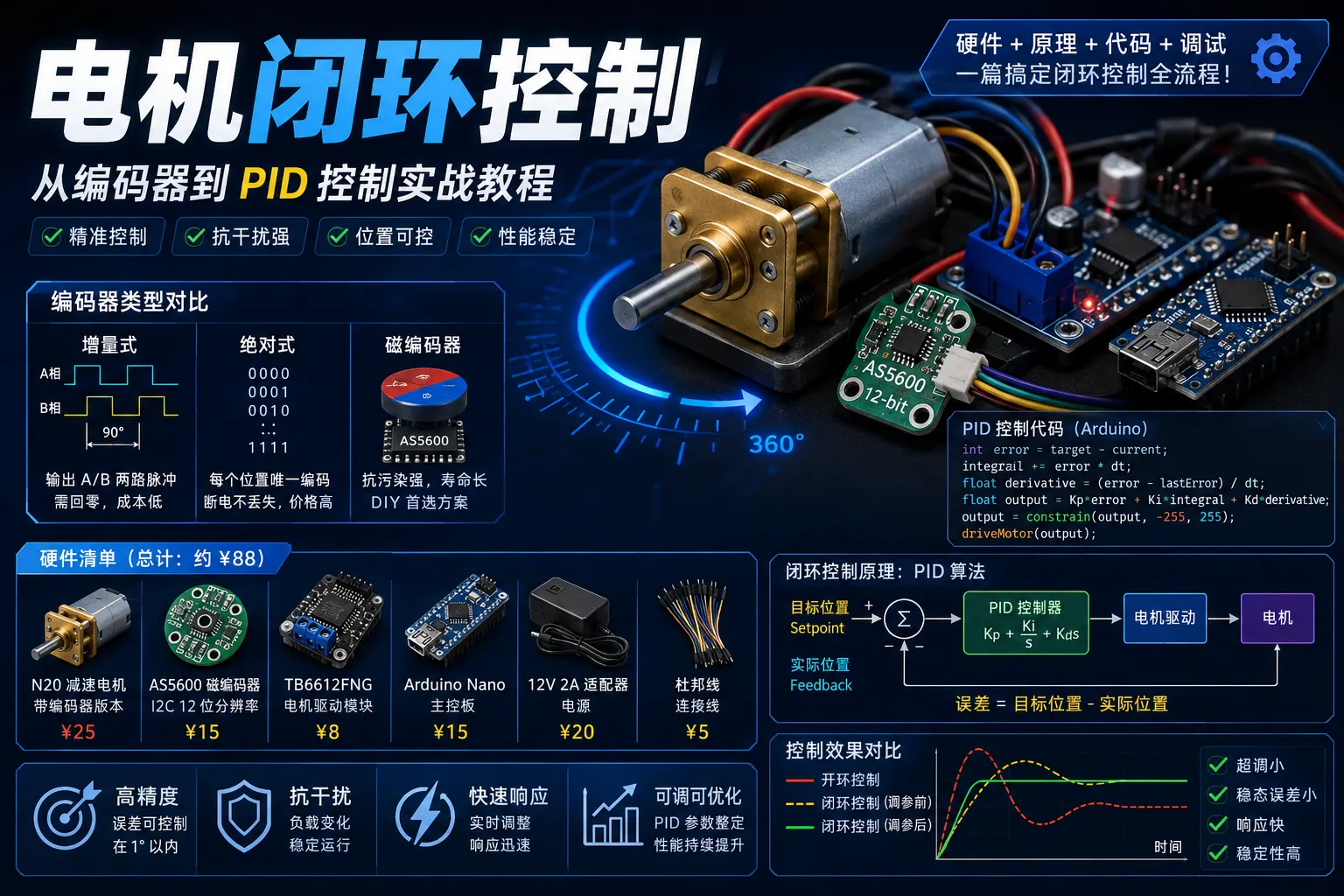
The fatal flaw of open-loop control: you don’t know how much the motor actually turned. Load changes, voltage fluctuations, and friction variations all cause the actual position to deviate from the expected one. Closed-loop control uses real-time encoder feedback for precise control — which is why CNC machines and robot joints all use closed-loop systems.
4.2 Encoder Types
| Type | Accuracy | Cost | Contamination Resistance | Typical Resolution |
|---|---|---|---|---|
| Optical | High | Medium | Poor | 1000-5000 PPR |
| Magnetic | Medium | Low | Good | 100-4096 PPR |
| Capacitive | High | High | Moderate | 1000-10000 PPR |
For DIY projects, the magnetic encoder AS5600 is recommended (I2C interface, 12-bit resolution, ¥15).
4.3 PID Control Principle
Error = Target Position - Actual Position
Output = Kp×Error + Ki×∫Error + Kd×d(Error)/dt- P (Proportional): Larger error → larger output. P alone has steady-state error
- I (Integral): Accumulates historical error to eliminate steady-state error. Too much causes overshoot
- D (Derivative): Predicts error trend to suppress overshoot. Sensitive to noise
4.4 Complete Closed-Loop Position Control Code
#include <Wire.h>
#include <AS5600.h>

AS5600 as5600;

const int PWM_PIN = 9;
const int IN1_PIN = 7;
const int IN2_PIN = 8;

// PID parameters
float Kp = 2.0, Ki = 0.5, Kd = 1.0;

int targetPosition = 0;
float integral = 0;
float lastError = 0;
unsigned long lastTime = 0;

void setup() {
  Serial.begin(115200);
  Wire.begin();
  as5600.begin(Wire);
  pinMode(PWM_PIN, OUTPUT);
  pinMode(IN1_PIN, OUTPUT);
  pinMode(IN2_PIN, OUTPUT);
  analogWrite(PWM_PIN, 0);
}

void loop() {
  if (Serial.available()) {
    targetPosition = Serial.parseInt();
    integral = 0;
    lastError = 0;
  }

  int currentPosition = as5600.readAngle();  // 0-4095
  int error = targetPosition - currentPosition;
  unsigned long currentTime = millis();
  float dt = (currentTime - lastTime) / 1000.0;

  if (dt > 0) {
    integral += error * dt;
    float derivative = (error - lastError) / dt;
    float output = Kp * error + Ki * integral + Kd * derivative;
    output = constrain(output, -255, 255);
    driveMotor(output);
    lastError = error;
    lastTime = currentTime;
  }

  Serial.print("Pos: "); Serial.print(currentPosition);
  Serial.print(" Err: "); Serial.print(error);
  Serial.print(" Out: "); Serial.println((int)output);
  delay(10);  // 100Hz control frequency
}

void driveMotor(float pwm) {
  if (pwm > 0) {
    digitalWrite(IN1_PIN, HIGH);
    digitalWrite(IN2_PIN, LOW);
    analogWrite(PWM_PIN, (int)pwm);
  } else {
    digitalWrite(IN1_PIN, LOW);
    digitalWrite(IN2_PIN, HIGH);
    analogWrite(PWM_PIN, (int)(-pwm));
  }
}
4.5 PID Tuning Tips
- P first, then D, then I: Start by increasing Kp until the system responds but begins to oscillate, then add Kd to damp oscillation, and finally add Ki to eliminate steady-state error
- Keep the control frequency stable: Use a timer rather than delay to ensure a fixed sampling period
- Integral clamping: Prevent integral windup
- Dead zone: Stop output when error is below a threshold to avoid continuous micro-adjustments that cause wear
4.6 Practical Application Scenarios
- Gimbal cameras: Stabilize the camera, counteract hand shake
- Robot joints: Precisely control robotic arm angles
- Self-balancing vehicles: Real-time motor adjustments to maintain balance
- CNC feed axes: Precise tool position control
- Winches: Constant tension control
5. Solar Charge Controllers: PWM vs MPPT
5.1 PWM vs MPPT Comparison
| Feature | PWM | MPPT |
|---|---|---|
| Conversion Efficiency | 60%~75% | 90%~98% |
| Cost | ¥20~50 | ¥100~500+ |
| Circuit Complexity | Low | High |
| Low Temp / Cloudy Performance | Average | Significantly better |
| DIY Difficulty | ★★☆☆☆ | ★★★★☆ |
Recommendation: PWM is sufficient for small 12V systems (solar panel under 20W); for systems above 20W or to maximize solar energy harvest, go with MPPT.
5.2 PWM Charge Controller DIY
Core idea: Use a MOSFET as a switch, controlled by an MCU that adjusts duty cycle based on battery voltage. Total cost approximately ¥20.
Three charging stages (for 12V lead-acid batteries):
typedef enum {
    CHARGE_BULK,        // Constant current (full power)
    CHARGE_ABSORPTION,  // Constant voltage (gradually reducing current)
    CHARGE_FLOAT,       // Float charge (low current maintenance)
    CHARGE_OFF          // Charging stopped
} ChargeState_t;
5.3 MPPT Perturb & Observe Method
The core of MPPT is a DC-DC buck converter with a tracking algorithm. Total cost approximately ¥65.
void mppt_algorithm(void) {
    uint16_t v_solar = read_solar_voltage();
    uint16_t i_solar = read_solar_current();
    uint32_t power = (uint32_t)v_solar * i_solar / 1000;

    uint32_t delta_p = power - prev_power;
    int16_t delta_v = v_solar - prev_voltage;

    if (delta_p > 0) {
        // Power increased — continue perturbing in the same direction
        if (delta_v > 0) set_buck_duty(get_buck_duty() - duty_step);
        else set_buck_duty(get_buck_duty() + duty_step);
    } else {
        // Power decreased — reverse the perturbation direction
        if (delta_v > 0) set_buck_duty(get_buck_duty() + duty_step);
        else set_buck_duty(get_buck_duty() - duty_step);
    }
    prev_voltage = v_solar;
    prev_power = power;
}
How Perturb & Observe works:
- Each iteration adjusts the voltage/duty cycle by a small step (e.g., 50mV)
- Measure the solar panel’s output power before and after the adjustment
- If power increases, the adjustment direction is correct — continue in the same direction
- If power decreases, the direction was wrong — reverse it
- Repeat until the system stabilizes near the maximum power point
5.4 Solar Panel Sizing
Solar Panel Power (W) = Battery Capacity (Ah) × Battery Voltage (V) ÷ Effective Sun Hours × System EfficiencyExample for a 12V 50Ah lead-acid battery: 600Wh ÷ 5h ÷ 0.75 ≈ 160W
5.5 Lithium vs Lead-Acid Battery Charging Parameters
| Parameter | 12V Lead-Acid | 12V Li-ion (4S) |
|---|---|---|
| Bulk Voltage | 14.4V | 16.8V |
| Absorption Voltage | 13.8V | 16.8V |
| Float Voltage | 13.2V | 14.6V |
| Low Voltage Cutoff | 11.5V | 12.0V |
| Max Charge Current | 0.1C~0.25C | 0.5C~1C |
Warning: Lithium batteries must always be used with a BMS! The charge controller manages only the charging curve — the BMS provides the final safety safeguard.
Summary
This guide covers five core areas of motor control:
| Topic | Key Chip/Module | Core Skills |
|---|---|---|
| Stepper Motor | A4988 | Microstepping config, Vref current adjustment, AccelStepper library |
| Servo | SG90/MG996 | PWM pulse width calibration, dead zone handling, multi-servo coordination |
| DC Motor | L298N | H-bridge control, PWM speed control, soft start, differential steering |
| Closed-Loop Control | AS5600 + TB6612 | PID tuning, encoder reading, position/speed closed-loop |
| Solar Control | STM32 + MOSFET | PWM/MPPT charging strategies, perturb & observe method |
From open-loop to closed-loop, from a single motor to multi-axis coordination — mastering these topics will prepare you for the vast majority of embedded motor control projects. Suggested learning path: DC motor PWM → Stepper motor open-loop → Servo angle control → Encoder closed-loop PID → Solar power system.
Hope this complete guide is helpful!