 Embedded Development
 Getting Started with Edge AI on ESP32-S3: A Hands-On TinyML Image Recognition Tutorial
Introduction
“Edge AI” has been gaining serious traction in the hardware community over the past couple of years. Many people hear “AI” and immediately think GPUs, cloud computing, and racks of expensive servers. But in reality, a development board costing just a few dollars — like the ESP32-S3 — is already capable of running simple image classification models.
In this article, we’ll walk through building an offline image recognition system from scratch using an ESP32-S3 and an OV2640 camera. No internet connection, no cloud services — all inference runs locally. Once you’ve completed this project, you’ll understand the fundamental TinyML workflow and be able to extend it to your own smart home, industrial inspection, or security monitoring applications.
Why the ESP32-S3?
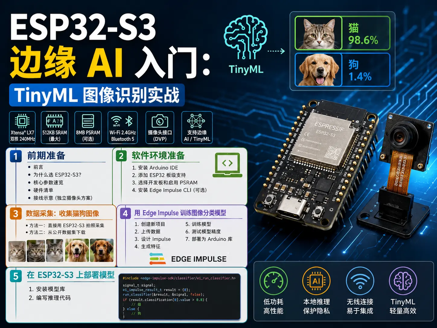
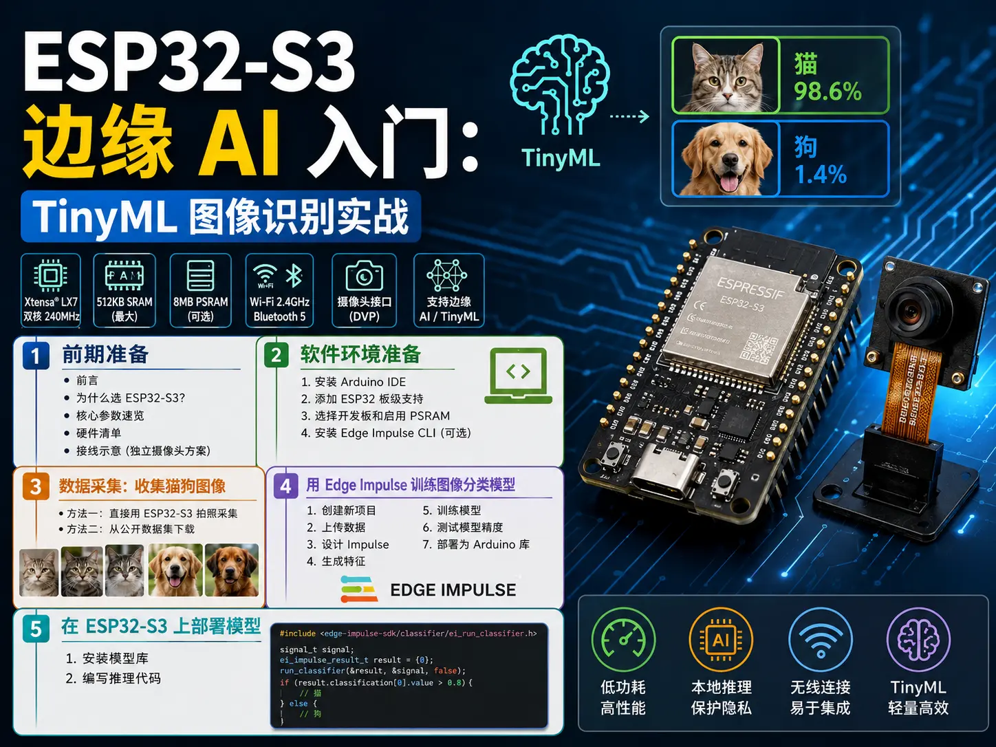
The ESP32-S3 is a dual-core Xtensa LX7 processor chip launched by Espressif in 2021, clocked at 240 MHz with 512 KB of on-chip SRAM and optional external PSRAM. Compared to the original ESP32, the S3’s biggest upgrade is the addition of Vector Instructions, specifically designed to accelerate neural network inference.
According to official benchmarks, the ESP32-S3 runs lightweight CNN models like MobileNetV1 2–3× faster than the original ESP32. Combined with built-in WiFi and Bluetooth, it’s an excellent fit for low-power edge AI nodes.
Key Specifications at a Glance
| Parameter | Specification |
|---|---|
| CPU | Dual-core Xtensa LX7 @ 240 MHz |
| SRAM | 512 KB internal + up to 8 MB external PSRAM |
| Flash | Up to 16 MB |
| Wireless | WiFi 802.11 b/g/n + Bluetooth 5 LE |
| Acceleration | AI Vector Instructions (matrix multiplication acceleration) |
| Camera Interface | DVP parallel interface (OV2640/OV5640) |
Hardware Checklist
Before getting started, gather the following hardware:
-
ESP32-S3 development board: We recommend the Seeed Studio XIAO ESP32S3 Sense or an ESP32-S3-CAM module. The XIAO series is compact with fewer pins, ideal for prototyping; the CAM module comes with a built-in camera ribbon connector for easier wiring.
-
OV2640 camera module: 2 megapixels with JPEG output. If you get the XIAO ESP32S3 Sense expansion board, the camera is already integrated.
-
MicroSD card (optional): For storing captured image datasets — a 4 GB+ Class 10 card is recommended.
-
USB-C data cable: For flashing firmware and serial debugging.
-
Breadboard and jumper wires: Needed if you’re using a standalone camera module and wiring it manually.
Wiring Diagram (Standalone Camera Setup)
If you’re using an ESP32-S3 DevKit with a standalone OV2640 module, here’s the wiring:
OV2640        ESP32-S3
--------      --------
VCC           3.3V
GND           GND
SIOC          GPIO 23
SIOD          GPIO 18
VSYNC         GPIO 38
HREF          GPIO 47
PCLK          GPIO 12
D0-D7         GPIO 11, 9, 8, 10, 7, 6, 5, 4
RESET         GPIO 15 (or connect to 3.3V)
PWDN GPIO 48 (or connect to GND)Note: Camera pin assignments may vary across different development boards — always consult your board’s schematic. The XIAO ESP32S3 Sense camera pins are pre-configured in the board definition file, so no manual wiring is needed.
Software Environment Setup
1. Install Arduino IDE
Download the latest Arduino IDE (2.x or 1.8.x both work) from arduino.cc.
2. Add ESP32 Board Support
Open Arduino IDE, go to File > Preferences, and add the following URL to “Additional Board Manager URLs”:
https://raw.githubusercontent.com/espressif/arduino-esp32/gh-pages/package_esp32_index.jsonThen go to Tools > Board > Board Manager, search for esp32, and install the esp32 package by Espressif Systems (version 2.0.8 or later recommended).
3. Select Your Board and Enable PSRAM
-
Tools > Board: Select your ESP32-S3 model (e.g.,
XIAO_ESP32S3orESP32S3 Dev Module). -
Tools > PSRAM: Select
OPI PSRAMorQSPI PSRAM(depending on your board’s actual configuration). This step is critical — camera frame buffers require significant memory, and failing to enable PSRAM will result in a build that compiles but crashes at runtime.
4. Install Edge Impulse CLI (Optional)
If you want to train models using the Edge Impulse platform, you’ll need Node.js and the Edge Impulse CLI:
npm install -g edge-impulse-cliData Collection: Gathering Cat and Dog Images
The first step in machine learning is collecting a dataset. We’ll tackle a classic “cat vs. dog” binary classification task.
Method 1: Capture Photos Directly with ESP32-S3
Seeed Studio provides a ready-made camera example that saves camera frames to the SD card. Here’s how:
-
Open Arduino IDE and load the camera example: Go to File > Examples > ESP32 > Camera > CameraWebServer (or CameraWebClient, depending on your board support package version). This example initializes the camera and streams live video over WiFi. If you only need to capture photos locally to the SD card, File > Examples > ESP32 > Camera > TakePicture is a better fit.
-
Modify pin configuration and SD card settings: At the top of the code, find the
camera_configstruct and adjust the camera pin definitions for your board. If using the XIAO ESP32S3 Sense, selectXIAO_ESP32S3under Tools > Board and the pins will auto-configure. Also verify the SD card CS pin is set correctly (typically GPIO 21 on the XIAO expansion board). -
Upload and run: Select the correct COM port and click Upload. Once complete, open the Serial Monitor (baud rate 115200). If everything is working, you’ll see
Camera Readyand eitherSD Card Mount Failed(if no card is inserted) orSD Card initialized. Each time you press the button on the board (or at the interval defined in code), the camera captures a photo and saves it as/photo.jpg. -
Check the photos on your SD card: Power off, remove the MicroSD card, and read it on your computer. You’ll find a collection of 2-megapixel JPEG photos. Aim to capture at least 200 photos per class (cat/dog) across different scenes, angles, and lighting conditions — the more diverse your data, the better your model will generalize. Once done, upload to Edge Impulse for training using Method 2 below.
Method 2: Download from a Public Dataset
If you’d rather not take photos yourself, you can use the Cat and Dog dataset on Kaggle, which contains tens of thousands of labeled images. Download it and select a subset (200–500 images per class is sufficient) for training.
Training an Image Classification Model with Edge Impulse
Edge Impulse is an ML development platform for embedded devices, providing an end-to-end pipeline from data collection to model training to deployment. After creating a free account, follow these steps:
1. Create a New Project
Log in to edgeimpulse.com, click Create new project, and name it cat-dog-classifier.
2. Upload Data
Go to the Data acquisition page, click Upload data, select “Select a folder”, and upload your folders of cat and dog images. Edge Impulse will automatically infer labels from folder names (e.g., images in a cat folder get the label cat).
After uploading, make sure the training/test split is roughly 80:20.
3. Design the Impulse
Go to the Impulse design page and click Create impulse. Configure as follows:
-
Input block: Image (96×96 pixels, RGB)
-
Processing block: Image (preprocessing)
-
Learning block: Transfer Learning (Images)
Click Save impulse.
4. Generate Features
Go to the Image processing block, keep the default parameters (Resize mode: Fit shortest axis), and click Generate features. This step converts raw images into numerical features the model can work with.
5. Train the Model
Go to the Transfer Learning block and configure:
-
Architecture: MobileNetV2 0.1 (the lightest variant, suitable for ESP32-S3)
-
Training cycles: 30
-
Learning rate: 0.0005
Click Start training. Training takes approximately 5–10 minutes depending on dataset size.
6. Test Model Accuracy
After training, go to the Model testing page and click Classify all. Ideally, test set accuracy should fall between 85%–95%. If it’s too low, you may need to increase your dataset size or adjust training parameters.
7. Deploy as an Arduino Library
Go to the Deployment page, select Arduino Library, and click Build. Download the generated .zip file.
Deploying the Model on ESP32-S3
1. Install the Model Library
In Arduino IDE, go to Sketch > Include Library > Add .ZIP Library and select the Edge Impulse library file you just downloaded.
2. Write the Inference Code
Below is a complete inference example — the camera captures frames in real time, each frame is classified by the model, and results are output over serial:
#include
#include "edge-impulse-sdk/classifier/ei_run_classifier.h"
#include "model-parameters/model_metadata.h"

// Camera configuration (modify pins for your actual hardware)
#define PWDN_GPIO_NUM     48
#define RESET_GPIO_NUM    -1
#define XCLK_GPIO_NUM     12
#define SIOD_GPIO_NUM     18
#define SIOC_GPIO_NUM     23
#define Y9_GPIO_NUM       11
#define Y8_GPIO_NUM       9
#define Y7_GPIO_NUM       8
#define Y6_GPIO_NUM       10
#define Y5_GPIO_NUM       7
#define Y4_GPIO_NUM       6
#define Y3_GPIO_NUM       5
#define Y2_GPIO_NUM       4
#define VSYNC_GPIO_NUM    38
#define HREF_GPIO_NUM     47
#define PCLK_GPIO_NUM     12

static camera_config_t camera_config = {
    .pin_pwdn  = PWDN_GPIO_NUM,
    .pin_reset = RESET_GPIO_NUM,
    .pin_xclk = XCLK_GPIO_NUM,
    .pin_sscb_sda = SIOD_GPIO_NUM,
    .pin_sscb_scl = SIOC_GPIO_NUM,
    .pin_d7 = Y9_GPIO_NUM,
    .pin_d6 = Y8_GPIO_NUM,
    .pin_d5 = Y7_GPIO_NUM,
    .pin_d4 = Y6_GPIO_NUM,
    .pin_d3 = Y5_GPIO_NUM,
    .pin_d2 = Y4_GPIO_NUM,
    .pin_d1 = Y3_GPIO_NUM,
    .pin_d0 = Y2_GPIO_NUM,
    .pin_vsync = VSYNC_GPIO_NUM,
    .pin_href = HREF_GPIO_NUM,
    .pin_pclk = PCLK_GPIO_NUM,
    .xclk_freq_hz = 20000000,
    .ledc_timer = LEDC_TIMER_0,
    .ledc_channel = LEDC_CHANNEL_0,
    .pixel_format = PIXFORMAT_JPEG,
    .frame_size = FRAMESIZE_QVGA,
    .jpeg_quality = 12,
    .fb_count = 1,
    .fb_location = CAMERA_FB_IN_PSRAM,
    .grab_mode = CAMERA_GRAB_WHEN_EMPTY,
};

void setup() {
    Serial.begin(115200);

    // Initialize camera
    esp_err_t err = esp_camera_init(&camera_config);
    if (err != ESP_OK) {
        Serial.printf("Camera init failed with error 0x%x\n", err);
        return;
    }

    Serial.println("Camera ready");
}

void loop() {
    // Capture a frame
    camera_fb_t *fb = esp_camera_fb_get();
    if (!fb) {
        Serial.println("Camera capture failed");
        return;
    }

    // Decode JPEG to RGB and resize to 96x96
    signal_t signal;
    float features;

    // Simplified here: in a real project you need libjpeg for decoding
    // and bilinear interpolation to resize to the model input dimensions

    // Run inference
    ei_impulse_result_t result = {0};
    EI_IMPULSE_ERROR res = run_classifier(&signal, &result, false);

    if (res == EI_IMPULSE_OK) {
        for (size_t ix = 0; ix < result.classifier_results_count; ix++) {
            Serial.printf("%s: %.4f\n", result.classification[ix].label, result.classification[ix].value);
        }
    }

    // Release frame buffer
    esp_camera_fb_return(fb);

    delay(1000);
}Note: The code above is a simplified version. In actual deployment, Edge Impulse generates complete preprocessing code (including JPEG decoding and image resizing). You just need to import the generated library into Arduino IDE and call run_classifier().
3. View Inference Results
After uploading the code, open the Serial Monitor and you’ll see output like this:
cat: 0.9234
dog: 0.0766
This means the current frame was classified as “cat” with 92.34% confidence.
Performance Optimization Tips
The ESP32-S3 has limited resources, so keep these tips in mind to keep your model running smoothly:
1. Lower the Input Resolution
MobileNetV2 defaults to 96×96 or 160×160 input. Lower resolution means faster inference, but also reduced accuracy. For simple classification tasks, 96×96 is usually sufficient.
2. Use a Quantized Model
Edge Impulse supports INT8 quantization, which can shrink model size by 4× and speed up inference by 2–3×. Select Quantized (INT8) on the Deployment page.
3. Reduce Inference Frequency
You don’t need to run inference on every frame. Inference every 500 ms–1 s is often enough, or only trigger inference when motion is detected (using a PIR sensor or frame differencing).
4. Enable PSRAM
As mentioned earlier, both camera frame buffers and model weights require substantial memory. Make sure PSRAM is enabled in Arduino IDE, or you’ll encounter malloc failed errors.
Troubleshooting Common Issues
Q1: No serial output after uploading code
-
Check that the USB driver is installed correctly (Windows requires CP210x or CH340 drivers).
-
Confirm the baud rate is set to 115200.
-
Hold the BOOT button while pressing RESET to put the board into download mode.
Q2: Camera initialization fails (error 0x105)
-
Verify camera wiring is correct, especially the I2C pins (SIOD/SIOC).
-
Confirm PSRAM is enabled.
-
Try lowering
xclk_freq_hzto 10 MHz or below.
Q3: Inference results are NaN or all zeros
-
Check that image preprocessing is correct (RGB channel order, normalization range).
-
Confirm the model input dimensions match the data you’re actually feeding in.
-
Review the example code generated by Edge Impulse and compare preprocessing logic.
Q4: Out-of-memory reboot
-
Reduce the number of simultaneously allocated frame buffers (set
fb_countto 1). -
Use a smaller model (MobileNetV2 0.1 instead of 0.35).
-
Enable INT8 quantization.
Next Steps
Once you’ve completed this foundational project, here are some directions to explore:
-
Multi-class classification: Expand to more categories — fruit recognition, gesture detection, or industrial part identification.
-
Object detection: Use YOLOv5-Tiny or SSD-MobileNet for object localization (requires more powerful hardware, such as ESP32-S3 + external NPU).
-
Face detection: Combine FaceNet or MTCNN to build a facial recognition access control system.
-
Low-power optimization: Leverage the ESP32-S3’s deep sleep mode, waking the camera and model only when motion is detected.
Conclusion
The ESP32-S3 may not be able to run large models, but for tasks like simple image classification, keyword spotting, and anomalous vibration detection, it’s more than capable. The key is understanding the TinyML workflow: Data Collection → Model Training → Quantization → Edge Deployment. Once you’ve mastered this methodology, you can apply it to any resource-constrained embedded scenario.
Hopefully this article helps you take your first steps into edge AI. If you have questions, feel free to leave a comment!