 ESP32
ESP32 Complete Guide to ESP32 Advanced Features: EEPROM Storage + UART Serial + OTA Wireless Updates
Introduction
The ESP32 is far more than just a Wi-Fi and Bluetooth-enabled IoT chip — it packs a wealth of powerful yet often overlooked features that let developers go from “internet-connected gadgets” all the way to “mass-producible products.” Many beginners stop at blinking LEDs and connecting to Wi-Fi, missing the capabilities that truly make the ESP32 worth diving into.
This article covers 3 advanced features every ESP32 developer should master:
- EEPROM for power-loss-proof data storage — let your device remember its state even after a restart;
- UART serial communication — use 3 hardware UARTs for reliable communication with sensors and modules;
- Wi-Fi OTA wireless updates — update firmware remotely without a USB cable.
Each section includes complete Arduino code and answers to frequently asked questions. Bookmark this and practice along!
Part 1: ESP32 Programming Basics
Before diving into advanced features, let’s quickly review the ESP32’s hardware capabilities and development environment setup to lay the groundwork for what follows.
ESP32 Core Specifications
The ESP32 is a low-cost, low-power System-on-Chip (SoC) from Espressif Systems, integrating Wi-Fi 802.11 b/g/n and Bluetooth v4.2 + BLE. Key parameters of its chip architecture include:
- Processor: High-performance Xtensa® 32-bit LX6 dual-core microprocessor, clocked up to 240 MHz
- Memory: 448 KB ROM + 520 KB SRAM + 16 KB SRAM in cache
- Operating Voltage: 2.2V ~ 3.6V
- Operating Temperature: -40°C ~ +125°C
Rich peripheral interfaces make the ESP32 suitable for a wide range of applications:
- 34 programmable GPIO pins
- Capacitive touch sensors
- Hall effect sensor
- SD card interface, Ethernet
- High-speed SPI, I2S, I2C, UART, ADC, and DAC
Setting Up the Development Environment
Arduino IDE is the preferred development environment for ESP32 programming. Here’s how to set it up:
- Open Arduino IDE, go to Preferences, and add the following URL to Additional Boards Manager URLs:
https://dl.espressif.com/dl/package_esp32_index.json - Go to Tools > Board > Boards Manager, search for
esp32, and install the package for your board model (common boards include ESP32-DevKitC, ESP-WROVER-KIT, etc.). - In Tools, select your board model, the correct serial port (COM port), and install the CP210x USB to UART Bridge VCP driver.
Hardware connections require: a USB data cable (for programming + power), a power module, an antenna (for Wi-Fi/Bluetooth signal), and peripherals such as LEDs, buttons, and sensors.
WiFi Connection Example
#include <WiFi.h>

const char* ssid = "your_wifi_ssid";
const char* password = "your_wifi_password";

void connectWiFi(){
  WiFi.begin(ssid, password);
  while(WiFi.status() != WL_CONNECTED){
    delay(1000);
    Serial.print(".");
  }
  Serial.println("WiFi Connected!");
  Serial.print("IP Address: ");
  Serial.println(WiFi.localIP());
}

void setup(){
  Serial.begin(115200);
  connectWiFi();
}

void loop(){}
Bluetooth Serial Example
#include "BluetoothSerial.h"

BluetoothSerial ESP_BT;

void setup(){
  Serial.begin(115200);
  ESP_BT.begin("ESP32_BT");
  Serial.println("Bluetooth Started!");
}

void loop(){
  if (ESP_BT.available()) {
    Serial.write(ESP_BT.read());
  }
  if (Serial.available()) {
    ESP_BT.write(Serial.read());
  }
  delay(20);
}
With these basics covered, we can now move on to the three advanced topics: EEPROM, UART, and OTA.
Part 2: EEPROM for Power-Loss-Proof Data Storage
What is EEPROM
EEPROM stands for Electrically Erasable Programmable Read-Only Memory — a type of electronic memory that can be erased and rewritten without requiring external equipment. It is a non-volatile memory (NVM), meaning data is retained even when power is removed. EEPROM is widely used in computers, smartphones, digital cameras, and various other electronic devices.
EEPROM Characteristics in the ESP32
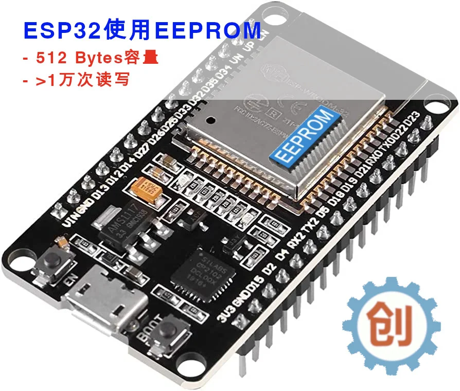
It’s important to note that the ESP32 does not have built-in hardware EEPROM — instead, it emulates EEPROM using Flash memory. Flash is very similar to EEPROM in that it is also non-volatile, making it ideal for storing data that needs to persist long-term. The emulated EEPROM on the ESP32 has the following characteristics:
- Non-volatile storage: Data is retained after power loss, suitable for long-term storage of configuration and state data
- Byte-addressable: Each address stores one byte (8 bits) of data, accessible directly by address index
- Limited write cycles: Flash-emulated EEPROM supports approximately 100,000 to 1,000,000 erase/write cycles
- Software-emulated: The ESP32 uses the EEPROM library to read and write on a dedicated Flash partition
How to Use It
Using EEPROM requires just 5 steps:
- Include the EEPROM library:
#include <EEPROM.h> - Initialize EEPROM:
EEPROM.begin(size)to specify the required storage space (in bytes) - Write data:
EEPROM.write(address, value)to write data to a specific address - Read data:
EEPROM.read(address)to read one byte from a specific address - Commit writes:
EEPROM.commit()to actually write the buffered data to Flash — this step must not be omitted
Complete Code Example: Saving LED State Across Power Cycles
The following code demonstrates how to save the LED state before power-off. Using a NodeMCU board, the default BUILDIN_LED is GPIO2. Pressing the IO0 button toggles the LED state, which is written to EEPROM in real time and restored after a power cycle.
// Include header files
#include <EEPROM.h>

// Define EEPROM size
#define EEPROM_SIZE 1
// Define pin — use the board's IO0 button, which is pulled HIGH by default
#define BUTTON_PIN 0
// Use the onboard LED
#define BUILDIN_LED 2

// LED state
int ledState = HIGH;
// Button state
int buttonState;
// Previous button state
int lastButtonState = HIGH;

// Time of last trigger
unsigned long lastDebounceTime = 0;
// Debounce timer
unsigned long debounceDelay = 50;

void setup() {
  Serial.begin(115200);

  // Initialize EEPROM
  EEPROM.begin(EEPROM_SIZE);

  // GPIO0 needs internal pull-up enabled
  pinMode(BUTTON_PIN, INPUT_PULLUP);
  pinMode(BUILDIN_LED, OUTPUT);

  // Read LED state from EEPROM
  ledState = EEPROM.read(0);
  // Restore state from before power-off
  digitalWrite(BUILDIN_LED, ledState);
}

void loop() {
  // Read button state
  int reading = digitalRead(BUTTON_PIN);

  // Check if button state changed
  if (reading != lastButtonState) {
    // Reset debounce timer
    lastDebounceTime = millis();
  }

  if ((millis() - lastDebounceTime) > debounceDelay) {
    // Must be pressed longer than debounce delay to register a state change
    // If button state has changed
    if (reading != buttonState) {
      buttonState = reading;

      // Only toggle LED when the new state is LOW
      if (buttonState == LOW) {
        ledState = !ledState;
      }
    }
  }
  // Save the reading we just took
  lastButtonState = reading;

  // If LED state differs from current output
  if (digitalRead(BUILDIN_LED) != ledState) {
    Serial.println("State changed");
    // Update LED
    digitalWrite(BUILDIN_LED, ledState);
    // Save LED state to EEPROM
    EEPROM.write(0, ledState);
    EEPROM.commit();
    Serial.println("State saved in flash memory");
  }
}
Common Use Cases
- WiFi credential storage: Automatically reconnect to the last configured WiFi after a reboot
- Device configuration parameters: Sensor thresholds, sampling intervals, device IDs, etc.
- Calibration data: Temperature/humidity sensor offset values, ADC zero-point calibration, etc.
- Runtime counters: Boot count, error count, uptime statistics
Part 3: UART Serial Communication
What is UART
UART stands for Universal Asynchronous Receiver/Transmitter — a hardware feature that handles the timing requirements and data framing of communication using widely adopted asynchronous serial interfaces such as RS232, RS422, and RS485. UART provides an inexpensive and widely used method for full-duplex or half-duplex data exchange between devices.
The ESP32 chip has 3 UART controllers (ports), each with an identical set of registers that simplifies programming while providing greater flexibility.
Serial Communication Process
Serial communication is controlled by a Finite State Machine (FSM) within each UART controller.
Steps for transmitting data:
- Write data to be sent into the UART’s TX FIFO buffer
- The FSM automatically assembles the data into serial frames according to the configured baud rate, data bits, stop bits, and parity bits
- Data is shifted out bit by bit through the TX pin to the receiver
Steps for receiving data:
- Once the RX pin detects the start bit (low level), the FSM begins sampling data bits at the configured baud rate
- The FSM assembles the sampled bits into complete bytes and stores them in the RX FIFO receive buffer
- The application reads the received data from the RX FIFO buffer
The application only needs to use uart_write_bytes() and uart_read_bytes() to operate on the specific buffers — the FSM handles everything else. More importantly, the ESP32 integrates FSM flow control directly into the chip and dedicates DMA (Direct Memory Access) for serial data processing. This makes hardware UART significantly more efficient than software serial and uses far less CPU resources.
UART Capabilities Across Different ESP32 Chips
Although ESP32 documentation states there are 3 serial controllers, the key factor affecting performance is whether the chip includes the corresponding Flow Control hardware and DMA hardware — and not all models have them:
Chips with two independent Flow Control + DMA units:
- ESP32-S (Ai-Thinker NodeMCU version)
- ESP32-S2
- ESP32-C3
Chips with three independent Flow Control + DMA units:
- ESP32 (ESP32-D0WD-V3, ESP32-D0WDR2-V3)
- ESP32-S3
ESP32 Hardware UART Pin Definitions
In the Arduino framework, the ESP32 defines Serial, Serial1, and Serial2 with the following pin assignments:
| UART | RX Pin | TX Pin | Notes |
|---|---|---|---|
| Serial | GPIO3 | GPIO1 | Can generally be used directly |
| Serial1 | GPIO9 | GPIO10 | By default, GPIO 6-12 are used for Flash interface and cannot be used by other programs |
| Serial2 | GPIO16 | GPIO17 | Can generally be used directly |
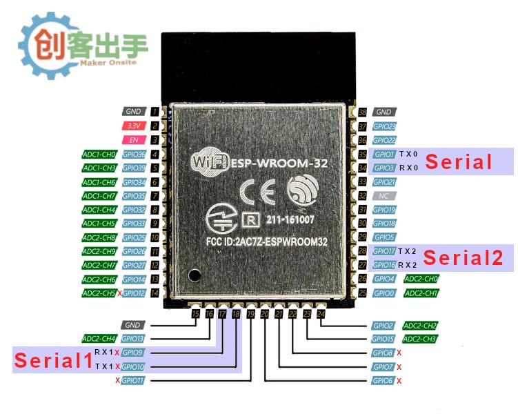
Why is Serial1 “Hard to Use”?
Serial1 defaults to GPIO9 and GPIO10, which fall within the GPIO 6-12 range — exactly the pins used by the ESP32’s internal Flash interface. Using Serial1 with its default configuration will conflict with Flash storage, causing the program to malfunction.
There are two solutions:
- Remap the pins: Use code to remap Serial1’s RX/TX pins to other GPIOs that are not occupied by Flash, avoiding the GPIO 6-12 range; alternatively, upload code via DIO mode to free up these pins.
- Use a SoftwareSerial library: Emulate a serial port on any general-purpose GPIO, but keep the baud rate low — suitable for low-speed communication scenarios.
Complete Code Example: Using Serial2
// To remap ports, modify the GPIO definitions below
// If using Serial1, you can upload code via DIO mode
//#define RXD1 9
//#define TXD1 10
#define RXD2 16
#define TXD2 17

void setup() {
  Serial.begin(115200);
  // Serial1.begin(9600, SERIAL_8N1, RXD1, TXD1);
  Serial2.begin(9600, SERIAL_8N1, RXD2, TXD2);
}

void loop() {
  // When Serial2 receives data, display it via Serial
  while (Serial2.available()) {
    Serial.print(char(Serial2.read()));
  }
}
Part 4: Wi-Fi OTA Wireless Updates
What is OTA
OTA stands for Over-The-Air — a technology for wireless downloading (and updating). It was initially widely adopted in the mobile phone industry, eliminating the cumbersome process of connecting to a computer, downloading software, and installing updates for phone upgrades.
For the ESP32, OTA means “wireless firmware upload” — you don’t need a USB cable to upload firmware to the ESP32. As long as the ESP32 and your computer are on the same network (Wi-Fi or Bluetooth), you can even update firmware via a web interface over the internet.
Why You Need OTA
OTA is a highly practical technology. Beyond convenience, it’s a lifesaver for ESP32 boards that have USB upload issues — since manufacturers use different components and designs, USB uploads can encounter various problems (such as auto-burn timeouts). If you include OTA support from the start of a project, you can still update firmware even if the USB port stops working.
How OTA Works
The OTA upgrade mechanism allows a device to update itself based on received data (via Wi-Fi or Bluetooth) while running normally. To enable OTA, you need to configure the device’s partition table, which must include at least:
- Two OTA application partitions:
ota_0andota_1 - One OTA data partition
When OTA is initiated, the system writes the new application firmware image to the OTA application partition that is not currently used for booting. After the image is verified, the OTA data partition is updated to specify using the new image on the next boot. The diagram below illustrates how the ESP32 uses partitions at different stages:
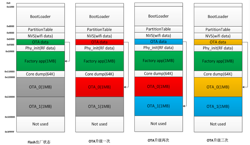
Updating via UDP OTA
Basic OTA uses the ArduinoOTA framework to support OTA operations. ESP32 boards supporting Basic OTA send UDP packets on the network, allowing your computer to discover OTA-capable devices. After selecting the device on the network as the port in Arduino IDE, you can perform over-the-air firmware updates:
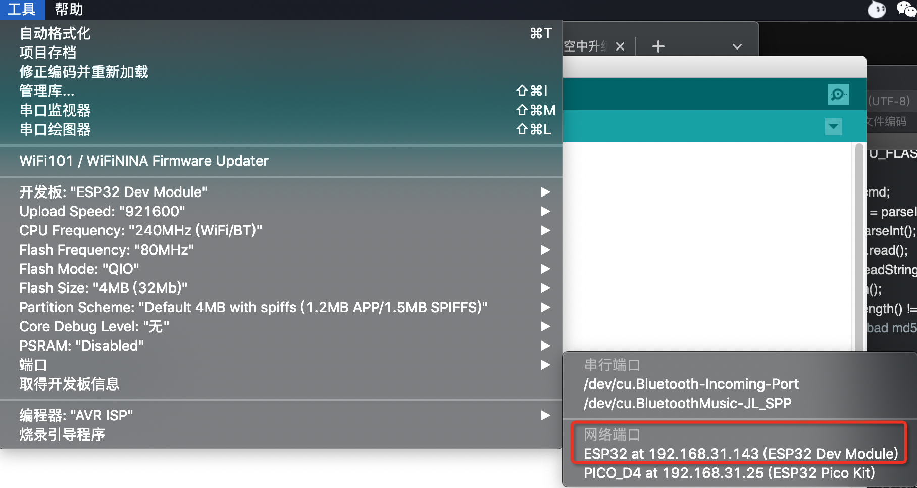
If you’re using PlatformIO, you can also perform OTA updates by replacing the port with an IP address. Modify or add the upload_port configuration in platformio.ini:
upload_port = 192.168.31.143You can also specify the upload_port via the pio command:
pio run -t upload --upload-port 192.168.31.143The same method works for uploading files to the ESP32’s SPIFFS or LittleFS.
Complete Code Example
Writing a program with OTA support only requires adding a small amount of code and configuration. Here’s a step-by-step walkthrough:
Step 1: Include header files
#include <WiFi.h>
#include <WiFiUdp.h>
#include <ArduinoOTA.h>
Step 2: Configure SSID and password
const char* ssid = "";
const char* password = "";
Step 3: Connect to Wi-Fi
void setup() {
  Serial.begin(115200);
  Serial.println("Booting");
  WiFi.mode(WIFI_STA);
  WiFi.begin(ssid, password);
  while (WiFi.waitForConnectResult() != WL_CONNECTED) {
    Serial.println("Connection Failed! Rebooting...");
    delay(5000);
    ESP.restart();
  }
Step 4: Set hostname for device identification
ArduinoOTA.setHostname("esp32_ota_test");Step 5: Add OTA callback handlers and start the OTA service
This code handles callbacks for OTA’s onStart, onEnd, onProgress, and onError events:
  ArduinoOTA
    .onStart([]() {
      String type;
      if (ArduinoOTA.getCommand() == U_FLASH)
        type = "sketch";
      else // U_SPIFFS
        type = "filesystem";

      // Note: if updating SPIFFS, you need to call SPIFFS.end() here
      Serial.println("Start updating " + type);
    })
    .onEnd([]() {
      Serial.println("\nEnd");
    })
    .onProgress([](unsigned int progress, unsigned int total) {
      Serial.printf("Progress: %u%%\r", (progress / (total / 100)));
    })
    .onError([](ota_error_t error) {
      Serial.printf("Error[%u]: ", error);
      if (error == OTA_AUTH_ERROR) Serial.println("Auth Failed");
      else if (error == OTA_BEGIN_ERROR) Serial.println("Begin Failed");
      else if (error == OTA_CONNECT_ERROR) Serial.println("Connect Failed");
      else if (error == OTA_RECEIVE_ERROR) Serial.println("Receive Failed");
      else if (error == OTA_END_ERROR) Serial.println("End Failed");
    });

  ArduinoOTA.begin();
}
Step 6: Add OTA handling in the loop method
void loop() {
  ArduinoOTA.handle();
}
Frequently Asked Questions
Question 1: Will an unexpected power loss or interruption during OTA affect the existing program?
Answer: It will not affect the existing program. The ESP32 allocates an OTA data partition, and only after a successful OTA does it specify using the OTA partition on the next boot. Therefore, an unexpected interruption during OTA will not corrupt the existing firmware — the device will still boot the old version normally.
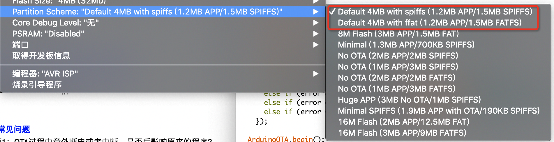
Question 2: Do all ESP32 chips support OTA?
Answer: No. When programming the ESP32, if you select a “No OTA” partition scheme, OTA functionality will not be available. Supporting OTA means the ESP32 needs both an APP data area and an OTA data area — your program space needs to occupy double the space to support OTA. Therefore, not all developers are willing to sacrifice double the space for OTA support; it depends on the actual needs of the project.
Summary
This article has covered 3 advanced features every ESP32 developer should master:
- EEPROM for power-loss-proof data storage: Gives your device “memory” for persistent storage of WiFi credentials, calibration parameters, runtime state, and other critical data — essential for productization;
- UART serial communication: The ESP32 has 3 hardware UARTs with Flow Control and DMA — understanding pin conflicts and remapping techniques is key to efficient communication with sensors and modules;
- Wi-Fi OTA wireless updates: Remote firmware updates without a USB cable, with partition table mechanisms ensuring safe upgrades — an essential operations tool after large-scale IoT device deployment.
Master these three features, and your ESP32 projects can truly go from “working demos” to “mass-producible products.” Happy developing!