 IoT
IoT Thread Protocol and IoT Security: Mesh Network Setup + Firmware Hardening Practice
Thread is one of the most noteworthy technologies in the IoT field in recent years. As a low-power Mesh network protocol based on IPv6, led by Google Nest, Thread is rapidly becoming the “universal language” for smart home device interconnection. However, with large-scale device deployment, security issues also arise - your firmware could be directly read from the Flash chip, with WiFi passwords, API keys, and private protocol logic all exposed in plaintext.
Today’s article will cover two dimensions of practice: building a Thread Mesh network + IoT firmware security hardening, making your IoT devices both interconnected and secure.
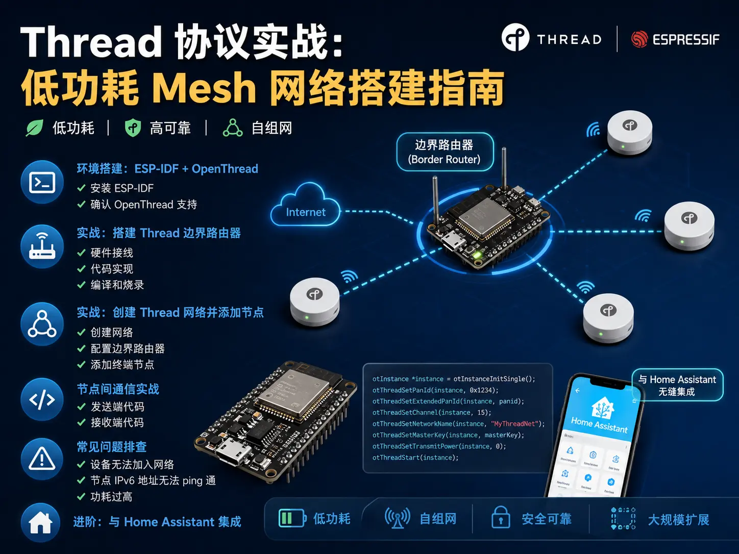
Part 1: Thread Mesh Network Setup
What is Thread? Why is it Worth Paying Attention To?
Thread is a wireless Mesh network protocol based on the IEEE 802.15.4 standard, operating in the 2.4GHz band. Its core advantages can be summarized in three points:
First, native IPv6 support. Each Thread device has an independent IPv6 address and can directly communicate with the internet without requiring an additional protocol translation layer. This is completely different from Zigbee - Zigbee devices need a gateway for address mapping, while Thread devices are “internet citizens” by nature.
Second, strong self-healing capability. Thread uses a Mesh topology, where devices can relay and forward data to each other. If a node goes offline, the network will automatically find new routing paths without causing the entire network to collapse.
Third, extremely low power consumption. Thread devices in sleep state can reduce current to the microamp level, and a single coin cell battery can make a sensor work for years. This is crucial for battery-powered smart home devices.
Currently, Thread has received support from giants like Apple, Google, Amazon, and Samsung, and has become the underlying network technology for the Matter protocol. It can be said that mastering Thread is mastering the key to future smart homes.
Hardware Preparation List
| Component | Recommended Model | Quantity | Price Reference |
|---|---|---|---|
| Border Router | ESP32-H2-DevKitC-1 or ESP32-C6-DevKitC-1 | 1 board | ¥25-35 |
| End Device | ESP32-H2-MINI-1 module or ESP32-C6 development board | 2-3 boards | ¥15-25/board |
| USB to Serial Cable | Type-C data cable | 3 cables | ¥10/cable |
| Breadboard + Jumper Wires | Universal 830-hole breadboard | 1 set | ¥15 |
| Sensors (optional) | DHT22 temperature/humidity sensor, PIR motion sensor module | 1 each | ¥10-15 |
Selection advice: ESP32-H2 is a chip specifically designed by Espressif for Thread/Zigbee, with lower power consumption; ESP32-C6 supports both Wi-Fi 6 and Thread, suitable for use as a Border Router.
Environment Setup: ESP-IDF + OpenThread
# Clone ESP-IDF repository
git clone -b v5.2 --recursive https://github.com/espressif/esp-idf.git
cd esp-idf
./install.sh esp32h2,esp32c6
. ./export.sh
ESP-IDF v5.0 and above has built-in OpenThread protocol stack, which can be confirmed with the following command:
idf.py --list-targets | grep -E "esp32h2|esp32c6"Practice: Building a Thread Border Router
The border router is the bridge between the Thread network and external networks (Wi-Fi or Ethernet), responsible for address allocation, routing forwarding, and network management.
#include "esp_log.h"
#include "esp_event.h"
#include "esp_netif.h"
#include "esp_wifi.h"
#include "esp_openthread.h"
#include "esp_openthread_border_router.h"
#include "openthread/instance.h"
#include "openthread/tasklet.h"

static const char *TAG = "Thread_BR";
#define WIFI_SSID "your_wifi_ssid"
#define WIFI_PASS "your_wifi_password"

static void wifi_event_handler(void *arg, esp_event_base_t event_base,
                               int32_t event_id, void *event_data)
{
    if (event_id == WIFI_EVENT_STA_START) {
        esp_wifi_connect();
    } else if (event_id == WIFI_EVENT_STA_DISCONNECTED) {
        esp_wifi_connect();
    } else if (event_id == IP_EVENT_STA_GOT_IP) {
        ip_event_got_ip_t *event = (ip_event_got_ip_t *)event_data;
        ESP_LOGI(TAG, "Wi-Fi connected, IP: " IPSTR, IP2STR(&event->ip_info.ip));
    }
}

static void init_wifi(void)
{
    ESP_ERROR_CHECK(esp_netif_init());
    ESP_ERROR_CHECK(esp_event_loop_create_default());
    esp_netif_create_default_wifi_sta();
    wifi_init_config_t cfg = WIFI_INIT_CONFIG_DEFAULT();
    ESP_ERROR_CHECK(esp_wifi_init(&cfg));
    esp_event_handler_instance_register(WIFI_EVENT, ESP_EVENT_ANY_ID,
                                        &wifi_event_handler, NULL, NULL);
    esp_event_handler_instance_register(IP_EVENT, IP_EVENT_STA_GOT_IP,
                                        &wifi_event_handler, NULL, NULL);
    wifi_config_t wifi_config = { .sta = { .ssid = WIFI_SSID, .password = WIFI_PASS } };
    ESP_ERROR_CHECK(esp_wifi_set_mode(WIFI_MODE_STA));
    ESP_ERROR_CHECK(esp_wifi_set_config(WIFI_IF_STA, &wifi_config));
    ESP_ERROR_CHECK(esp_wifi_start());
}

void app_main(void)
{
    ESP_LOGI(TAG, "Starting Thread Border Router...");
    init_wifi();
    esp_openthread_platform_config_t config = {
        .radio_config = { .radio_mode = RADIO_MODE_NATIVE },
        .port_config = {
            .storage_partition_name = "nvs",
            .netif_queue_size = 10,
            .task_queue_size = 10,
        },
    };
    ESP_ERROR_CHECK(esp_openthread_init(&config));
    ESP_ERROR_CHECK(esp_openthread_border_router_init());
    ESP_LOGI(TAG, "Thread Border Router started!");
    while (1) {
        otTaskletsProcess(esp_openthread_get_instance());
        usleep(100000);
    }
}
Compile and flash:
idf.py set-target esp32c6
idf.py build
idf.py -p /dev/ttyACM0 flash monitor
Create Thread Network and Add Nodes
Create a network on the border router through OpenThread CLI:
> dataset init new
> dataset networkname MyThreadNet
> dataset panid 0x1234
> dataset networkkey 00112233445566778899aabbccddeeff
> dataset commit active
> ifconfig up
> thread start
> br enable
Join the network on the end device (ESP32-H2):
> dataset networkname MyThreadNet
> dataset panid 0x1234
> dataset networkkey 00112233445566778899aabbccddeeff
> dataset commit active
> ifconfig up
> thread start
> state
child
Seeing child or router status indicates the device has successfully joined the network.
UDP Communication Between Nodes
#include "openthread/udp.h"

void send_udp_message(otInstance *aInstance, const char *destAddr,
                      uint16_t port, const char *message)
{
    otIp6Address destination;
    otIp6AddressFromString(destAddr, &destination);
    otMessage *msg = otUdpNewMessage(aInstance, NULL);
    otMessageAppend(msg, message, strlen(message));
    otMessageInfo messageInfo = {0};
    messageInfo.mPeerPort = port;
    messageInfo.mPeerAddr = destination;
    otUdpSendDatagram(aInstance, msg, &messageInfo);
}
Common Problem Troubleshooting
Problem 1: Device Cannot Join Network (end device always shows detached)
- Confirm that the border router and end device’s Network Name, PAN ID, and Network Key are all exactly the same
- Check if both have the same Channel set (default Channel 15), can use
dataset channel 15to force specification - Ensure the end device and border router are within RF coverage range (recommend no more than 5 meters for initial testing)
- Use the
statecommand to confirm the border router is inleaderorrouterstate, notdetached
Problem 2: Node IPv6 Address Cannot Be Pinged
- Execute
router tableon the border router to confirm the child node appears in the routing table - Check if border routing function is enabled (
br enable), otherwise external networks cannot reach the Thread subnet - Confirm the firewall is not blocking ICMPv6 packets, Thread networks rely on ICMPv6 for neighbor discovery
- Use the
ipaddrcommand to confirm the node has obtained a Mesh Local address (fdde:ad00:beef::prefix)
Problem 3: Power Consumption Too High
otLinkModeConfig mode;
mode.mRxOnWhenIdle = false;
mode.mSecureDataRequests = true;
mode.mDeviceType = false;
otThreadSetLinkMode(esp_openthread_get_instance(), mode);
otLinkSetPollPeriod(esp_openthread_get_instance(), 5000);
Part 2: IoT Firmware Security Hardening
The network is set up, next we need to solve an equally important issue: firmware security. Many developers just flash the ESP32 program and run it, never considering - someone could take the board apart, use an SPI programmer to read the Flash, and the entire firmware is in their hands.
Why Do Firmware Security?
Suppose you made a smart door lock, with ESP32 responsible for Bluetooth communication and motor control. A competitor buys the product, opens the case, uses a programmer to read all the Flash data - Bluetooth pairing keys, unlock protocols, cloud API secret keys are all exposed in plaintext.
Secure Boot + Flash Encryption solve two core problems:
- Prevent firmware tampering: Only firmware signed with your private key can run on the device, attackers cannot implant malicious code
- Prevent firmware reverse engineering: Flash content is hardware-encrypted, even physically reading the chip yields no useful information
ESP32 (v3.0 and above chip versions) supports Secure Boot v2, based on the RSA-PSS signature scheme. Use esptool chip_id to check the chip version.
Core Concept: Chain of Trust
ROM code (immutable) → Verify secondary bootloader signature → Verify App firmware signature → Run application- After the chip powers on, the code固化 in ROM executes first, using the public key digest burned in eFuse to verify the RSA signature of the secondary bootloader
- After the bootloader passes verification, it continues to verify the application firmware signature using the same mechanism
- Only after all verifications pass is control handed over to the application
Key point: The private key is never stored on the device, it only exists on your development computer or offline environment. The device only has the public key digest (eFuse), even if an attacker gets the board they cannot forge signatures.
Step 1: Generate Signing Key
idf.py secure-generate-signing-key signing_key.pemThis will generate an RSA-3072 PEM format key. Be sure to keep it safe: backup to an offline USB drive, don’t upload to Git, use HSM or offline computer for production environments. You can also manually generate with OpenSSL:
openssl genrsa -out signing_key.pem 3072Step 2: Configure menuconfig
Run idf.py menuconfig:
Security features →
  [✓] Enable hardware Secure Boot in bootloader
  Secure Boot Version → Secure Boot V2 (RSA-PSS)
  (/path/to/signing_key.pem) Signing key file path

Component config → ESP32-specific →
  Minimum Supported ESP32 Revision → v3.0

Security features →
  [✓] Enable flash encryption on boot (RELEASE_ON_BOOT)
Flash encryption mode → DEVELOPMENT / RELEASE- DEVELOPMENT mode: Automatically re-encrypts on each flash, convenient for debugging
- RELEASE mode: Only encrypts once, Flash content permanently encrypted
Warning: After disabling UART download mode, you will not be able to reflash via serial port. Keep it open during development, turn it off before mass production.
Step 3: Build and Flash
# Build bootloader
idf.py bootloader
# Manually flash bootloader
esptool.py --port /dev/ttyUSB0 write_flash 0x0 build/bootloader/bootloader.bin
# Flash App
idf.py flash
After reset you should see:
I (xxx) boot: Secure boot V2 enabled
I (xxx) boot: Validating app image...
I (xxx) boot: App image verified successfully
Verify Security Effects
Test 1: Flash unsigned firmware - Device refuses to start, serial output shows Secure boot verification failed! Halting...
Test 2: Read Flash -
esptool.py --port /dev/ttyUSB0 read_flash 0x0 0x400000 flash_dump.binIn RELEASE mode, flash_dump.bin content is completely encrypted and cannot be decompiled.
OTA Upgrade Signing
OTA firmware must be signed with the same private key:
idf.py secure-sign-app build/app.bin signed_app.binESP32’s OTA mechanism automatically verifies signatures, rolling back on failure.
Common Issues
| Problem | Answer |
|---|---|
| Cannot flash after enabling secure boot | Don’t disable UART download mode during development, configure OTA or JTAG |
| Difficult to debug after Flash encryption | Use DEVELOPMENT mode during development |
| Can eFuse errors be recovered | No, eFuse is one-time programmable (OTP), please test thoroughly before writing |
| Performance impact | Boot adds about 100-200ms, runtime encryption/decryption is hardware accelerated with almost no loss |
Production Environment Best Practices
- Keep private keys offline: Store signing keys on an offline computer or HSM hardware security module, never online
- Use RELEASE mode: Switch production devices to RELEASE mode, Flash encryption takes effect permanently after one-time encryption
- Turn off UART download mode: Prevent attackers from injecting malicious firmware via serial port
- Enable anti-rollback: Configure eFuse security version counter to prevent firmware downgrade to old version vulnerabilities
- Regularly rotate keys: Use different key pairs for different product batches to limit the impact of single batch leakage
Summary
This article covers the complete chain from networking to security for IoT devices:
- Thread Protocol: Low power consumption, native IPv6, self-healing Mesh network, the underlying foundation for Matter smart homes
- Mesh Network Setup: ESP32-H2/C6 + OpenThread border router + end device network joining + UDP communication
- Firmware Security Hardening: Secure Boot v2 chain of trust + Flash encryption, preventing firmware reverse engineering and tampering
The combination of Thread and Matter is reshaping the smart home ecosystem, and security is the foundation of all this. As Makers, consider security and connectivity from the first project, rather than waiting until after product launch when it’s cracked to remediate.
Reference Resources: