 Hardware & Design
 SD Card Protocol Fully Explained: Evolution from SD 1.0 to SD 8.0, Bus Modes, and Speed Classes (2026 Practical Guide)
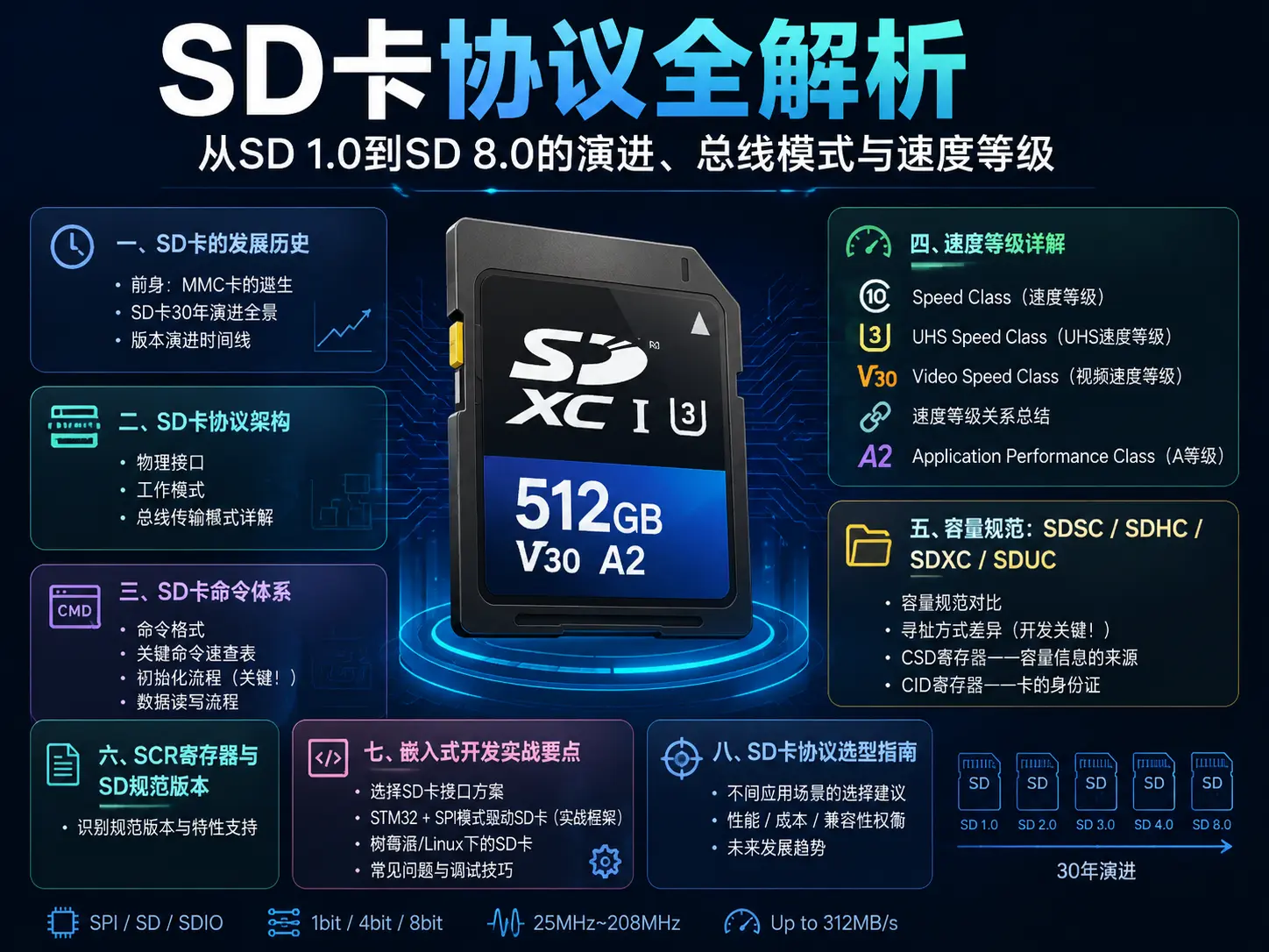
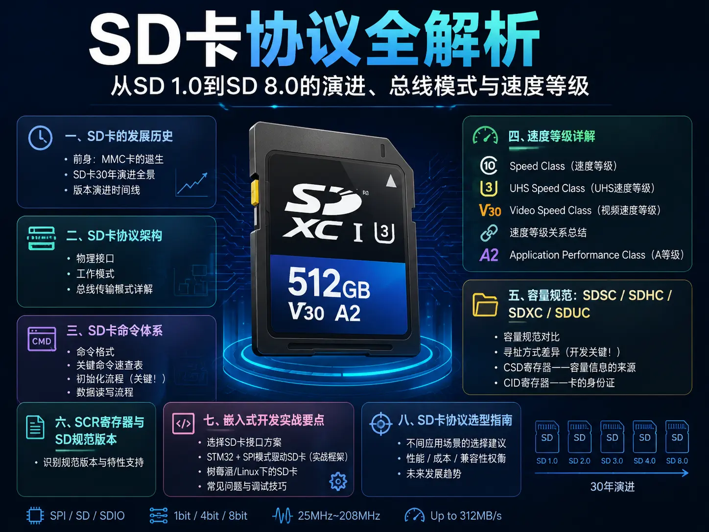
SD card (Secure Digital Memory Card) is currently one of the most widely used removable storage media, from digital cameras to embedded development boards, from drones to dash cams, almost ubiquitous. As a storage standard born in 1999, the SD card protocol has undergone multiple major evolutions, from an initial maximum capacity of 2GB to today’s theoretical limit of 128TB per card.
This article will comprehensively analyze the technical details of the SD card protocol from the perspectives of protocol evolution, bus interface, command system, speed grades, and capacity specifications, helping embedded engineers and hardware developers deeply understand this “small but powerful” storage protocol.
I. SD Card Development History
1.1 Predecessor: The Birth of MMC Card
To understand SD cards, one must first understand their predecessor—the MMC (MultiMediaCard). In 1997, Siemens and SanJointly developed the MMC card, adopting a 7-pin interface, with the design concept of miniaturization and low power consumption.
The birth of SD cards stemmed from an actual need: MMC cards lacked built-in encryption functionality. In 1999, Panasonic (Matsushita), Toshiba, and SanDisk three companies jointly established the SD Association (SD Association, abbreviated SDA), and based on MMC, launched the SD card standard. Key improvements include:
- Added an encryption (CPRM) register to achieve “Secure Digital”
- Increased the number of pins from 7 to 9, adding dedicated data transmission lines
- Raised the bus frequency from MMC’s 20MHz to 25MHz
- Introduced 4-bit parallel transmission mode
1.2 Panoramic View of SD Card’s 30-Year Evolution
From 1999 to now, the SD card protocol has experienced eight major version evolutions:
SD 1.0 (1999)
- Maximum capacity: 2GB (SDSC, Standard Capacity)
- Bus frequency: 25MHz
- Transfer modes: SPI, 1-bit SD mode
- Voltage range: 2.7V-3.6V
- Transfer rate: Up to 12.5MB/s (1-bit mode)
SD 1.1 (2001)
- Added 4-bit SD bus mode
- Introduced high-speed mode (High Speed Mode), frequency increased to 50MHz
- Transfer rate: Up to 25MB/s (4-bit high-speed mode)
SD 2.0 (2006)
- Milestone version, introduced SDHC (Secure Digital High Capacity) specification
- File system switched from FAT12/FAT16 to FAT32
- Maximum capacity: 32GB
- Introduced speed class (Speed Class): Class 2/4/6/10
- Bus frequency remains 25MHz/50MHz
- Added ACMD41 command support for high-capacity addressing (SDHC uses block addressing instead of byte addressing)
SD 3.0 (2010)
- Major upgrade, introduced UHS-I (Ultra High Speed Phase I) bus
- Introduced SDXC (Secure Digital eXtended Capacity) specification
- File system supports exFAT
- Maximum capacity: 2TB
- UHS-I bus frequency: 100MHz (DDR mode)
- UHS-I transfer rate: Up to 104MB/s
- Added UHS Speed Class: UHS-I (U1)
SD 4.0 (2011)
- Introduced UHS-II (Ultra High Speed Phase II)
- Added one row of pins (second row of contacts on the back), enabling full-duplex communication
- UHS-II bus speed: 312MB/s
- Introduced UHS Speed Class U3 (guaranteed minimum 30MB/s write)
- Introduced the embryonic form of Video Speed Class
SD 5.0 (2016)
- Introduced SDUC (Secure Digital Ultra Capacity) specification
- Maximum capacity: 128TB
- Added Video Speed Class: V6/V10/V30/V60/V90
- Introduced SD-Transport (SD Transport) for firmware updates
SD 6.0 (2018)
- Introduced UHS-III
- UHS-III full-duplex speed: 624MB/s
- Introduced new power management functions
- Supports lower voltage operation (1.2V signal level)
SD 7.0 (2018)
- Introduced SD Express, based on PCIe 3.0 and NVMe protocols
- Theoretical maximum speed: approaching 985MB/s
- Maintains backward compatibility with older SD cards (dual-mode design)
- Supports USB 3.2 protocol as an alternative
SD 8.0 (2023)
- Upgraded SD Express to PCIe 4.0
- Theoretical maximum speed: approximately 3938MB/s (x1 lane PCIe 4.0)
- Supports x2 lane PCIe configuration
- Further reduced power consumption design
1.3 Version Evolution Timeline
flowchart LR
    V1["SD 1.0<br>1999"]
    V11["SD 1.1<br>2001"]
    V2["SD 2.0<br>2006"]
    V3["SD 3.0<br>2010"]
    V4["SD 4.0<br>2011"]
    V5["SD 5.0<br>2016"]
    V6["SD 6.0<br>2018"]
    V7["SD 7.0<br>2018"]
    V8["SD 8.0<br>2023"]
    V1 -->|SDSC 2GB| V11
    V11 -->|4-bit, 50MHz| V2
    V2 -->|SDHC 32GB| V3
    V3 -->|SDXC 2TB<br>UHS-I 104MB/s| V4
    V4 -->|UHS-II 312MB/s| V5
    V5 -->|SDUC 128TB<br>Video Class| V6
    V6 -->|UHS-III 624MB/s| V7
    V7 -->|SD Express<br>PCIe 3.0 985MB/s| V8
II. SD Card Protocol Architecture
2.1 Physical Interface
The physical interface design of SD cards is one of its core innovations. Standard SD cards have 9 pins, MicroSD cards also have 9 pins but size reduced to 15mm × 11mm × 1mm.
Standard SD card pin definition (9-pin):
| Pin | Name | Function |
|---|---|---|
| 1 | CD/DAT3 | Card Detection / Data Line 3 |
| 2 | CMD | Command/Response Line (Bidirectional) |
| 3 | VSS1 | Ground |
| 4 | VDD | Power Supply (2.7V-3.6V) |
| 5 | CLK | Clock Signal |
| 6 | VSS2 | Ground |
| 7 | DAT0 | Data Line 0 |
| 8 | DAT1 | Data Line 1 |
| 9 | DAT2 | Data Line 2 |
UHS-II extended pins (back row):
UHS-II cards add an extra row of contacts on the back to achieve full-duplex data transmission:
| Position | Function |
|---|---|
| Back 1-2 | Differential Pair TX (Transmit) |
| Back 3-4 | Differential Pair RX (Receive) |
| Back 5-7 | Reserved/Ground |
Physical differences between MicroSD and standard SD cards:
| Parameter | Standard SD Card | MicroSD Card |
|---|---|---|
| Size | 32mm × 24mm × 2.1mm | 15mm × 11mm × 1mm |
| Weight | Approximately 2g | Approximately 0.25g |
| Pin Count | 9 | 8 (removing one DAT3/CD multiplexed) |
| Card Detection | Mechanical detection switch | Depends on insertion detection spring |
| Typical Applications | Cameras, voice recorders, industrial control boards | Smartphones, drones, action cameras, Raspberry Pi |
2.2 SD Card Working Modes
SD cards support two basic working modes, which is the first key fork in understanding the SD protocol:
SPI Mode (Serial Peripheral Interface Mode):
SPI mode is the most basic communication method of SD cards, using the standard SPI bus protocol. In this mode, the SD card essentially acts as an SPI slave device.
- Uses 4 lines: CLK, MOSI (CMD), MISO (DAT0), CS (DAT3)
- DAT1 and DAT2 pins are not used
- Communication protocol is simple, compatible with all MCUs with SPI interface
- Speed is relatively low, up to about 12.5MB/s (SDSC) or 25MB/s (SDHC)
- Key difference: SPI mode uses block addressing (Block Address), not byte addressing
MCU                    SD Card (SPI Mode)
-----                  -------------
SCK  ────────────── CLK
MOSI ────────────── CMD  (Command Input)
MISO ────────────── DAT0 (Data Output)
CS   ────────────── DAT3 (Chip Select, Active Low)
                     DAT1, DAT2 Not Used
SD Mode (SD Bus Mode / Native Mode):
SD mode is the native working mode of SD cards, using the dedicated bus protocol defined by the SD Association, supporting 1-bit, 4-bit, and even 8-bit parallel transmission.
- Uses all 9 pins (at least CMD + CLK + DAT0~DAT3, total 6 signal lines)
- Requires a dedicated SDIO controller (most SoCs have it built-in)
- Supports higher transfer rates (UHS-I/II/III)
- Supports full SD card functionality (UHS, SCR registers, ACMD commands, etc.)
MCU/SoC              SD Card (SD Mode)
---------            -------------
CLK  ────────────── CLK
CMD  ←─────────────→ CMD  (Bidirectional, Command/Response)
DAT0 ←─────────────→ DAT0 (Bidirectional, Data)
DAT1 ←─────────────→ DAT1 (Bidirectional, Data/Interrupt)
DAT2 ──────────────→ DAT2 (Data Direction)
DAT3 ←─────────────→ DAT3 (Data/Chip Select)
SPI Mode vs SD Mode Comparison:
| Feature | SPI Mode | SD Mode |
|---|---|---|
| Required Pins | 4 | 6 (1-bit)/ 6+ (4-bit) |
| Communication Protocol | Standard SPI | SD-dedicated Protocol |
| Maximum Speed | 25MB/s | Up to 3938MB/s (SD Express) |
| ACMD Command Support | Not Supported | Supported |
| UHS Support | Not Supported | Supported |
| Applicable Scenarios | Low-speed Embedded, MCU Resources Limited | High-performance Storage, Phones, Cameras |
| Driver Complexity | Low | High |
2.3 Bus Transmission Modes Explained
In SD mode (Native Mode), SD cards support multiple bus transmission modes, with speed increasing step by step:
1-bit SD Bus Mode:
- Uses only DAT0 one data line for transmission (CMD + CLK + DAT0, total 3 signal lines)
- Transmits 1 bit of data per clock cycle
- Default Mode (Default Speed): 25MHz, theoretical rate 3.125 MB/s
- High-Speed Mode (High Speed): 50MHz, theoretical rate 6.25 MB/s
- Suitable for pin-constrained scenarios
4-bit SD Bus Mode:
- Uses DAT0~DAT3 four data lines together
- Transmits 4 bits of data per clock cycle
- Default Mode (Default Speed): 25MHz × 4 = 12.5 MB/s
- High-Speed Mode (High Speed): 50MHz × 4 = 25 MB/s
- This is the most common SD card working mode, the vast majority of SD card readers and SoCs default to this mode
UHS-I (Ultra High Speed Phase I):
- Uses 4-bit bus, but adopts DDR (Double Data Rate) sampling
- Samples data on both rising and falling edges of the clock, effectively doubling the frequency
- Bus frequency: 100MHz (DDR), actual transfer rate 104 MB/s (SDR50) or 208 MB/s (DDR50)
- SDR104 mode: 208MHz clock, single-edge sampling, theoretical rate 104 MB/s
- Requires 1.8V signal level (achieved via CMD11 voltage switching)
UHS-II (Ultra High Speed Phase II):
- Uses the extra row of differential contacts (Lane) on the back
- Uses LVDS (Low Voltage Differential Signaling) differential signal
- Full-duplex communication (independent TX and RX differential pairs)
- Bus speed: 312 MB/s
- Mainly used for high-end cameras and video equipment
UHS-III (Ultra High Speed Phase III):
- Similarly uses the back differential contacts
- Full-duplex speed doubled to 624 MB/s
- Introduces new power management and flow control mechanisms
SD Express (SD 7.0 / 8.0):
- Runs PCIe 3.0/4.0 + NVMe protocol on the UHS-II/III differential contacts
- SD 7.0 (PCIe 3.0 x1): Theoretical rate 985 MB/s
- SD 8.0 (PCIe 4.0 x1): Theoretical rate 3938 MB/s
- Maintains backward compatibility—when inserted into a traditional SD card reader, automatically falls back to UHS-I/II mode
- Uses dual-mode design (Dual-mode): the card internally has both SD controller and PCIe/NVMe controller
Comparison of Various Bus Mode Rates:
| Mode | Bus Width | Clock Frequency | Sampling Method | Theoretical Rate | Signal Voltage |
|---|---|---|---|---|---|
| Default Speed | 1-bit | 25MHz | SDR | 3.125 MB/s | 3.3V |
| High Speed | 1-bit | 50MHz | SDR | 6.25 MB/s | 3.3V |
| Default Speed | 4-bit | 25MHz | SDR | 12.5 MB/s | 3.3V |
| High Speed | 4-bit | 50MHz | SDR | 25 MB/s | 3.3V |
| SDR50 | 4-bit | 100MHz | SDR | 50 MB/s | 1.8V |
| DDR50 | 4-bit | 50MHz | DDR | 50 MB/s | 1.8V |
| SDR104 | 4-bit | 208MHz | SDR | 104 MB/s | 1.8V |
| UHS-II | Differential Lane | — | LVDS | 312 MB/s | 1.8V |
| UHS-III | Differential Lane | — | LVDS | 624 MB/s | 1.8V |
| SD Express (PCIe 3.0) | Differential Lane | — | PCIe | 985 MB/s | 1.8V |
| SD Express (PCIe 4.0) | Differential Lane | — | PCIe | 3938 MB/s | 1.8V |
III. SD Card Command System (CMD Instruction Set)
All operations of SD cards are completed through commands (Command). Understanding the command system is the core of embedded development for driving SD cards.
3.1 Command Format
In SD mode, the command frame length is 48 bits (standard command) or 136 bits (long response command), structured as follows:
Standard Command Format (48 bit):
┌──────────┬──────────┬──────────┬──────────┬──────────┐
│ Start bit│Transmit  │ CMD Index│ Argument │ CRC7     │ End bit │
│  (1 bit) │ Direction│ (6 bit) │ (32 bit) │ (7 bit)  │ (1 bit) │
│    0     │   1 bit  │          │          │          │    1    │
└──────────┴──────────┴──────────┴──────────┴──────────┴─────────┘- Start bit: Always 0, marks the beginning of the command
- Transmission bit: Host→Card is 0, Card→Host is 1
- CMD Index: Command number (CMD0
CMD63, ACMD0ACMM63) - Argument: 32-bit parameter, meaning varies by command
- CRC7: 7-bit check code (SPI mode CRC can be disabled for CMD0 and CMD8)
- End bit: Always 1
Response Types:
After executing a command, the SD card returns a response (Response), with multiple response types:
| Response Type | Length | Typical Command | Content |
|---|---|---|---|
| R1 | 48 bit | Most commands | Card Status Register + CMD Index |
| R1b | 48 bit + Busy | CMD7, CMD12 | R1 + Busy Signal (DAT0 pulled low) |
| R2 | 136 bit | CMD9, CMD10 | CID/CSD Register Complete Content |
| R3 | 48 bit | ACMD41 | OCR Register (no CRC) |
| R6 | 48 bit | CMD3 | RCA (Relative Card Address) + Status |
| R7 | 48 bit | CMD8 | Voltage Support + Check Mode Echo |
3.2 Key Command Quick Reference
The following are the most commonly used commands in SD card development:
| Command | Name | Description | Parameter |
|---|---|---|---|
| CMD0 | GO_IDLE_STATE | Reset card, enter Idle state | None |
| CMD2 | ALL_SEND_CID | All cards send CID (serial number, etc.) | None |
| CMD3 | SEND_RELATIVE_ADDR | Card returns relative address (RCA) | None |
| CMD5 | SLEEP_AWAKE | Sleep/wake (UHS-II) | RCA |
| CMD7 | SELECT/DESELECT_CARD | Select/deselect card | RCA |
| CMD8 | SEND_IF_COND | Voltage compatibility check (SD 2.0+ required) | Voltage+check mode |
| CMD9 | SEND_CSD | Read CSD register (capacity/speed info) | RCA |
| CMD10 | SEND_CID | Read CID register | RCA |
| CMD12 | STOP_TRANSMISSION | Stop multi-block read/write transmission | None |
| CMD13 | SEND_STATUS | Query card status | RCA |
| CMD16 | SET_BLOCKLEN | Set block length (SDSC used, SDHC ignored) | Block size |
| CMD17 | READ_SINGLE_BLOCK | Read single data block | Address |
| CMD18 | READ_MULTIPLE_BLOCK | Continuously read multiple data blocks | Address |
| CMD24 | WRITE_BLOCK | Write single data block | Address |
| CMD25 | WRITE_MULTIPLE_BLOCK | Continuously write multiple data blocks | Address |
| CMD55 | APP_CMD | Application command prefix (next is ACMD) | RCA |
| ACMD6 | SET_BUS_WIDTH | Set bus width (1-bit or 4-bit) | 0=1bit, 2=4bit |
| ACMD41 | SD_SEND_OP_COND | SD card initialization (send OCR, get capability) | OCR |
| ACMD51 | SEND_SCR | Read SCR register (SD specification version) | None |
3.3 SD Card Initialization Process (Crucial!)
SD card initialization is the most complex and critical part of driver development. Below is the complete initialization process:
sequenceDiagram
    participant Host
    participant SD卡
    Host->>SD卡: CMD0 (GO_IDLE_STATE) — Reset card
    Host->>SD卡: CMD8 (SEND_IF_COND) — arg: 0x1AA
    SD卡-->>Host: R7 — Voltage compatibility echo
    Note over Host,SD卡: Correct response=SD2.0+; no response=SD1.x

    loop Loop until busy bit=1 (timeout approx 1s)
        Host->>SD卡: CMD55 + ACMD41 (HCS=1)
        SD卡-->>Host: R3 (OCR)
    end
    Note over Host: CCS=1→SDHC(block addressing)<br>CCS=0→SDSC(byte addressing)

    Host->>SD卡: CMD2 (ALL_SEND_CID)
    SD卡-->>Host: R2 (CID)
    Host->>SD卡: CMD3 (SEND_RELATIVE_ADDR)
    SD卡-->>Host: R6 (RCA)
    Host->>SD卡: CMD9 (SEND_CSD)
    SD卡-->>Host: R2 (CSD)
    Host->>SD卡: CMD7 (SELECT)
    SD卡-->>Host: R1b
    Host->>SD卡: CMD55 + ACMD6 — Switch to 4-bit
    Note over Host,SD卡: Initialization complete, enter Data Transfer state
Key Details:
- CMD8 is the watershed for distinguishing SD 1.x and SD 2.0+. If your code only supports SD 1.x, it will be unable to use SDHC/SDXC cards.
- ACMD41 must be triggered via CMD55 prefix (CMD55 tells the card “the next command is ACMD”).
- The HCS bit (Host Capacity Support) of ACMD41 must be set to 1, otherwise the card will think the host only supports SDSC, and SDHC cards will refuse initialization.
- Initialization loop requires timeout mechanism, usually set to 1 second. The card may need hundreds of ACMD41 commands before becoming ready.
3.4 Data Read/Write Process
After initialization completes, typical data read/write flow is as follows:
Single Block Read (CMD17):
sequenceDiagram
    participant Host
    participant SD卡
    Host->>SD卡: CMD17 (Address)
    SD卡-->>Host: R1
    SD卡-->>Host: Data Block<br>Start(0xFE) + 512B + CRC16
Multiple Block Read (CMD18):
sequenceDiagram
    participant Host
    participant SD卡
    Host->>SD卡: CMD18 (Address)
    SD卡-->>Host: R1
    SD卡-->>Host: Data Block 1
    SD卡-->>Host: Data Block 2
    SD卡-->>Host: ...
    Host->>SD卡: CMD12 (STOP)
    SD卡-->>Host: R1b
Multiple Block Write (CMD25)—Note Pre-erase:
sequenceDiagram
    participant Host
    participant SD卡
    Host->>SD卡: CMD25 (Address)
    SD卡-->>Host: R1
    Host->>SD卡: Data Block 1<br>Start(0xFC) + 512B + CRC16
    SD卡-->>Host: Data Response (Accept/Reject)
    Host->>SD卡: Data Block 2
    SD卡-->>Host: Data Response
    Host->>SD卡: CMD12 (STOP)
    SD卡-->>Host: R1b (Wait for programming completion)
IV. Speed Class Details
The speed class system of SD cards has been continuously complicated over 30 years, currently there are three parallel speed identification systems. Understanding them is key to correct model selection.
4.1 Speed Class (Speed Class)
The earliest speed identification (SD 2.0), represented by letter C surrounding a number:
| Level | Minimum Sustained Write Speed | Typical Application |
|---|---|---|
| Class 2 | 2 MB/s | Basically phased out |
| Class 4 | 4 MB/s | Low-resolution video recording |
| Class 6 | 6 MB/s | 720p video recording |
| Class 10 | 10 MB/s | 1080p full HD video, burst photography |
Note: Speed Class indicates minimum sustained write speed, not maximum read speed. A card labeled Class 10 may have read speeds up to 95MB/s, but write speed is guaranteed not lower than 10MB/s.
4.2 UHS Speed Class (UHS Speed Class)
Introduced with UHS-I bus (SD 3.0), represented by letter U surrounding a number:
| Level | Minimum Sustained Write Speed | Typical Application |
|---|---|---|
| U1 | 10 MB/s | 1080p real-time video |
| U3 | 30 MB/s | 4K video recording (30fps) |
UHS Class cards also simultaneously display traditional Speed Class (e.g., U3 cards usually also labeled Class 10).
4.3 Video Speed Class (Video Speed Class)
Introduced in SD 5.0, specifically designed for high-resolution video, represented by letter V plus a number:
| Level | Minimum Sustained Write Speed | Typical Application |
|---|---|---|
| V6 | 6 MB/s | Standard definition/720p video |
| V10 | 10 MB/s | 1080p full HD video |
| V30 | 30 MB/s | 4K @ 60fps video, VR content |
| V60 | 60 MB/s | 8K @ 30fps video, high bitrate 4K |
| V90 | 90 MB/s | 8K @ 60fps, professional movie-level shooting |
4.4 Speed Class Relationship Summary
flowchart TB
    Root["Speed Class System Evolution"]
    SC["Speed Class (2006)<br>Class 2 / 4 / 6 / 10"]
    UHS["UHS Speed Class (2010)<br>U1 / U3"]
    VSC["Video Speed Class (2016)<br>V6 / V10 / V30 / V60 / V90"]
    Note["Three systems used in parallel<br>V level is currently the recommended video selection standard"]
    Root --> SC
    Root --> UHS
    Root --> VSC
    VSC --> Note
Example of reading speed labels on a card:
┌─────────────────────────┐
│  SanDisk Extreme Pro    │
│  64GB  SDXC  U3  V30    │  ← SDXC capacity + U3 + V30
│  A2  Class 10           │  ← A2 application performance + Class 10
│  300 MB/s READ          │  ← Maximum read speed (manufacturer labeled, not standard)
└─────────────────────────┘
4.5 Application Performance Class (A Level)
Added in SD 5.1, measures random read/write performance (IOPS), important for running operating systems or apps:
| Level | Minimum Random Read IOPS | Minimum Random Write IOPS | Minimum Sustained Write |
|---|---|---|---|
| A1 | 1500 | 500 | 10 MB/s |
| A2 | 4000 | 2000 | 10 MB/s |
A2 level requires card support for command queue (Command Queue), and the host also needs to support the corresponding protocol. SBCs like Raspberry Pi using A2 cards can significantly improve system responsiveness.
V. Capacity Specifications: SDSC / SDHC / SDXC / SDUC
SD card capacity specifications are closely related to addressing methods, different capacity cards have essential behavioral differences.
5.1 Capacity Specification Comparison
| Specification | Introduced Version | Capacity Range | File System | Addressing Method |
|---|---|---|---|---|
| SDSC (Standard Capacity) | SD 1.0 | 1MB ~ 2GB | FAT12/FAT16/FAT32 | Byte Address |
| SDHC (High Capacity) | SD 2.0 | 2GB ~ 32GB | FAT32 | Block Address (512 bytes/block) |
| SDXC (eXtended Capacity) | SD 3.0 | 2GB ~ 2TB | exFAT | Block Address (512 bytes/block) |
| SDUC (Ultra Capacity) | SD 5.0 | 2GB ~ 128TB | exFAT | Block Address (512 bytes/block) |
5.2 Addressing Method Differences (Development Key!)
This is the easiest pitfall in embedded development:
SDSC cards use byte addressing (Byte Address):
- CMD17 read command parameter is the byte offset of data
- Read block 0: parameter = 0
- Read block 1: parameter = 512 (each block 512 bytes)
- Read block N: parameter = N × 512
SDHC/SDXC cards use block addressing (Block Address):
- CMD17 read command parameter is the block number
- Read block 0: parameter = 0
- Read block 1: parameter = 1
- Read block N: parameter = N
// Pseudocode: address conversion during read/write
if (card_type == SDSC) {
    // Byte addressing: address = block number × 512
    argument = block_number * 512;
} else {
    // SDHC/SDXC: block addressing, address is block number
    argument = block_number;
}
Why distinction needed? During initialization, determine via the CCS bit (Card Capacity Status) in the R3 response of ACMD41. CCS=1 indicates SDHC/SDXC (block addressing), CCS=0 indicates SDSC (byte addressing). If confused, read/write data positions will be completely wrong.
5.3 CSD Register—Source of Capacity Information
CSD (Card-Specific Data) register contains card capacity, speed, programming time, and other key information. Read via CMD9, length 128 bits.
CSD V1.0 (SDSC/SDHC) key fields:
| Field | Bit Range | Description |
|---|---|---|
| CSD_STRUCTURE | [127:126] | CSD version: 00=V1.0 (SDSC), 01=V2.0 (SDHC) |
| READ_BL_LEN | [83:80] | Maximum read block length (SDSC, usually 9=512B) |
| C_SIZE | [73:62] | Capacity multiplier (SDSC) |
| C_SIZE_MULT | [49:47] | Capacity multiplier factor |
| C_SIZE (V2.0) | [69:48] | SDHC capacity value (direct mapping) |
SDSC capacity calculation formula:
memory_capacity = (C_SIZE + 1) × (C_SIZE_MULT + 2) × (2 ^ READ_BL_LEN)SDHC/SDXC capacity calculation formula (V2.0):
memory_capacity = (C_SIZE + 1) × 512KBExample: C_SIZE = 60951 → capacity = 60952 × 512KB ≈ 30.4GB
5.4 CID Register—Card’s ID Card
CID (Card Identification) register contains card’s unique identification information, read via CMD10:
| Field | Length | Description |
|---|---|---|
| MID | 8 bit | Manufacturer ID (e.g., SanDisk=0x03, Samsung=0x1B) |
| OID | 16 bit | OEM/Application ID |
| PNM | 40 bit | Product name (ASCII string) |
| PRV | 8 bit | Product version |
| PSN | 32 bit | Product serial number |
| MDT | 12 bit | Production date (year/month) |
VI. SCR Register and SD Specification Version
SCR (SD Configuration Register) is a 64-bit register containing SD card specification version and bus capability information. Read via ACMD51 (requires CMD55 prefix).
SCR key fields:
| Field | Bit Range | Description |
|---|---|---|
| SCR_STRUCTURE | [63:60] | SCR version number |
| SD_SPEC | [59:56] | SD specification version: 0=1.0-1.01, 1=1.10, 2=2.00-3.0X |
| DATA_STAT_AFTER_ERASE | [55] | Data state after erase (0/1) |
| SD_SECURITY | [54:52] | Security support (CPRM etc.) |
| SD_BUS_WIDTHS | [51:48] | Supported bus widths (bit0=1bit, bit2=4bit) |
| SD_SPEC3 | [47] | SD 3.0+ support: 0=No, 1=Yes |
| SD_SPEC4 | [46] | SD 4.0+ support |
| SD_SPECX | [45:42] | SD 5.0+ extended version |
| CMD_SUPPORT | [35:32] | Supported commands (CMD23 etc.) |
Why SCR important? The SD_SPEC field can tell you which SD specification version this card follows, but cannot tell you which bus mode the host will use. Bus mode is determined through command negotiation during initialization, not unilaterally decided by the card.
VII. Embedded Development Practical Points
7.1 Choosing SD Card Interface Solution
In embedded projects, choosing SPI mode or SD mode depends on specific needs:
| Scenario | Recommended Solution | Reason |
|---|---|---|
| STM32/Arduino low-speed data logging | SPI mode | Simple driver, low MCU resource usage |
| Raspberry Pi/Linux SBC | SD mode (4-bit) | Kernel has driver, optimal performance |
| High-speed data acquisition (>25MB/s) | SD mode (UHS-I) | SPI mode cannot meet speed requirements |
| Extremely tight pin resources | SPI mode | Only needs 4 wires |
| Need card hot-plug detection | SD mode | DAT3 pin can do mechanical detection |
7.2 STM32 + SPI Mode SD Card Driver (Practical Framework)
Below is the core code framework for driving SD card via SPI interface using STM32 HAL library:
#include "stm32f4xx_hal.h"
#include <string.h>

// SD card type enumeration
typedef enum {
    SD_TYPE_SDSC,
    SD_TYPE_SDHC_SDXC
} SD_CardType;

// SD card information structure
typedef struct {
    SD_CardType type;
    uint32_t capacity_mb;      // Capacity (MB)
    uint8_t cid[16];           // CID register
    uint8_t csd[16];           // CSD register
} SD_CardInfo;

static SPI_HandleTypeDef hspi1;
static SD_CardInfo sd_info;

// CS chip select control
#define SD_CS_LOW()   HAL_GPIO_WritePin(GPIOA, GPIO_PIN_4, GPIO_PIN_RESET)
#define SD_CS_HIGH()  HAL_GPIO_WritePin(GPIOA, GPIO_PIN_4, GPIO_PIN_SET)

// SPI transfer single byte
static uint8_t SPI_TransferByte(uint8_t data) {
    uint8_t rx;
    HAL_SPI_TransmitReceive(&hspi1, &data, &rx, 1, 100);
    return rx;
}

// Send command and get response
static uint8_t SD_SendCommand(uint8_t cmd, uint32_t arg) {
    uint8_t response;
    uint8_t retry = 0;

    SD_CS_LOW();

    // Send command frame
    SPI_TransferByte(0x40 | cmd);      // Start + Direction + CMD Index
    SPI_TransferByte((arg >> 24) & 0xFF);  // Argument [31:24]
    SPI_TransferByte((arg >> 16) & 0xFF);  // Argument [23:16]
    SPI_TransferByte((arg >> 8) & 0xFF);   // Argument [15:8]
    SPI_TransferByte(arg & 0xFF);           // Argument [7:0]

    // CRC (only CMD0 and CMD8 need valid CRC)
    if (cmd == 0) SPI_TransferByte(0x95);  // CMD0 CRC
    else if (cmd == 8) SPI_TransferByte(0x87); // CMD8 CRC
    else SPI_TransferByte(0xFF);  // Fake CRC

    // Wait for response (remove start bit)
    do {
        response = SPI_TransferByte(0xFF);
        retry++;
    } while (response == 0xFF && retry < 100);

    SD_CS_HIGH();
    return response;
}

// SD card initialization
HAL_StatusTypeDef SD_Init(void) {
    uint8_t response;
    uint32_t retry;

    // 1. Power-on delay + send 74+ clock pulses
    HAL_Delay(10);
    SD_CS_HIGH();
    for (int i = 0; i < 10; i++) {
        SPI_TransferByte(0xFF);  // 80 clocks
    }

    // 2. CMD0 reset to Idle state
    retry = 0;
    do {
        response = SD_SendCommand(0, 0);
        retry++;
    } while (response != 0x01 && retry < 100);
    if (response != 0x01) return HAL_ERROR;  // Not entered Idle

    // 3. CMD8 check voltage compatibility
    response = SD_SendCommand(8, 0x000001AA);
    if (response == 0x01) {
        // SD 2.0+ card: read R7 response last 4 bytes
        uint8_t r7[4];
        for (int i = 0; i < 4; i++) r7[i] = SPI_TransferByte(0xFF);
        // Verify echo: r7[3] should be 0xAA
        sd_info.type = SD_TYPE_SDHC_SDXC;  // Assume SDHC
    } else {
        sd_info.type = SD_TYPE_SDSC;  // SD 1.x card
    }
    SD_CS_HIGH();

    // 4. ACMD41 loop initialization (until ready)
    retry = 0;
    do {
        SD_SendCommand(55, 0);  // CMD55 prefix
        uint32_t acmd41_arg = 0x40000000;  // HCS=1, support SDHC
        if (sd_info.type == SD_TYPE_SDSC) acmd41_arg = 0;
        response = SD_SendCommand(41, acmd41_arg);
        retry++;
        HAL_Delay(1);
    } while (response != 0x00 && retry < 200);
    if (response != 0x00) return HAL_ERROR;

    // 5. CMD16 set block length to 512 (SDSC needs)
    if (sd_info.type == SD_TYPE_SDSC) {
        SD_SendCommand(16, 512);
    }

    // 6. Read capacity (CMD9 reads CSD)... omitted, see CSD parsing

    return HAL_OK;
}

// Read single block (512 bytes)
HAL_StatusTypeDef SD_ReadBlock(uint32_t block_num, uint8_t *buf) {
    uint32_t addr;
    uint8_t token;
    uint32_t retry;

    // Address conversion
    if (sd_info.type == SD_TYPE_SDSC) {
        addr = block_num * 512;  // Byte address
    } else {
        addr = block_num;        // Block address
    }

    SD_CS_LOW();

    // Send CMD17
    if (SD_SendCommand(17, addr) != 0x00) {
        SD_CS_HIGH();
        return HAL_ERROR;
    }

    // Wait for data token (0xFE)
    retry = 0;
    do {
        token = SPI_TransferByte(0xFF);
        retry++;
    } while (token == 0xFF && retry < 10000);

    if (token != 0xFE) {
        SD_CS_HIGH();
        return HAL_ERROR;
    }

    // Read 512 bytes data
    for (int i = 0; i < 512; i++) {
        buf[i] = SPI_TransferByte(0xFF);
    }

    // Discard CRC16 (2 bytes)
    SPI_TransferByte(0xFF);
    SPI_TransferByte(0xFF);

    SD_CS_HIGH();
    return HAL_OK;
}
7.3 SD Card on Raspberry Pi/Linux
On Linux systems (like Raspberry Pi), the kernel has built-in SD card driver, usually no need to manually write driver code:
# View SD card information
cat /sys/block/mmcblk0/device/cid    # CID register
cat /sys/block/mmcblk0/device/csd    # CSD register
cat /sys/block/mmcblk0/size          # Capacity (512-byte block count)

# View SD card bus speed
cat /sys/block/mmcblk0/device/max_current
ls -la /sys/bus/mmc/devices/

# Test SD card read/write speed
sudo hdparm -tT /dev/mmcblk0

# View actual negotiated bus mode of SD card
dmesg | grep mmc
# Typical output:
# mmc0: new ultra high speed DDR50 SDHC card ...
# or: mmc0: new high speed SDHC card ...
7.4 Common Issues and Debugging Tips
Problem 1: SD card initialization fails (ACMD41 no response)
Checklist:
- Check SPI wiring (MOSI/MISO/CLK/CS) is secure
- Confirm SPI clock frequency during initialization phase does not exceed 400kHz (SD spec requirement)
- Check power supply stability (SD card initialization instantaneous current can reach 150mA)
- Ensure CS pin remains high for at least 74 clocks before initialization
Problem 2: Can initialize but read/write data garbled
Most common cause is address mode confusion:
- Check if correctly distinguished SDSC (byte address) and SDHC (block address)
- Use CMD9 to read CSD, confirm CSD_STRUCTURE field (0=SDSC, 1=SDHC)
// Debug: print CSD structure type
uint8_t csd_structure = (csd[0] >> 6) & 0x03;
printf("CSD Version: %s\n", csd_structure == 0 ? "V1.0 (SDSC)" : "V2.0 (SDHC/SDXC)");
Problem 3: High-speed mode negotiation fails
- UHS-I requires 1.8V signal level switching (CMD11 triggered)
- If host doesn’t support 1.8V switching, card falls back to 3.3V high-speed mode (25MB/s)
- Ensure PCB trace signal integrity (trace length <10cm, avoid vias)
Problem 4: Write speed slow
- Check if card’s speed class matches application needs
- SD card write requires erase before write, write speed affected by erase block size
- Using CMD23 (SET_BLOCK_COUNT) to pre-notify block count can improve multi-block write performance
- Ensure no write protection (check DAT1 pin status or card’s physical write protect switch)
Problem 5: Card not recognized
# Linux diagnose SD card recognition issues
dmesg | tail -20                    # View kernel log
lsblk                                # View block devices
sudo fdisk -l /dev/mmcblk0          # View partition
sudo mmc extcsd read /dev/mmcblk0   # View extended register (requires mmc-utils)
VIII. SD Card Protocol Selection Guide
According to different application scenarios, recommend selecting different SD card specifications:
| Application Scenario | Recommended Capacity Spec | Recommended Speed Class | Recommended Interface Mode | Selection Advice |
|---|---|---|---|---|
| Embedded data logging (low-speed) | SDSC/SDHC | Class 10 | SPI mode | Cost priority, 16GB sufficient |
| Raspberry Pi/Linux SBC | SDHC/SDXC | A2, V30 | SD mode (kernel driver) | A2 level significantly improves random IO |
| 4K video recording | SDXC | V30/U3 | SD mode | 64GB starting point, V30 guarantees sustained write |
| 8K professional photo/video | SDXC | V60/V90 | SD mode (UHS-II) | Requires UHS-II card slot support |
| Industrial temperature control/harsh environment | SDHC | Class 10 | SPI/SD mode | Choose industrial grade (-40°C~85°C) |
| IoT edge devices | MicroSD SDHC | Class 10/A1 | SPI mode | Note power consumption, choose low-power model |
Summary
SD card protocol has evolved over 30 years into a complex and perfected storage standard system. As an embedded engineer, understanding SD card protocol requires grasping the following core dimensions:
- Two working modes: SPI mode (simple low-speed) and SD mode (complex high-speed), choose according to project needs
- Bus evolution path: from 1-bit → 4-bit → UHS-I(DDR) → UHS-II(differential) → SD Express(PCIe), rate from 3MB/s to nearly 4GB/s
- Command system: CMD0
CMD63 + ACMD0ACMD63, where initialization process (CMD0→CMD8→ACMD41→CMD2→CMD3→CMD7) is the core of driver development - Speed grades: three parallel systems (Class/UHS Class/Video Class) + A level (random IO), V level is the preferred standard for video applications
- Capacity and addressing: SDSC uses byte addressing, SDHC/SDXC uses block addressing—this is the most error-prone detail in embedded development
For most embedded projects, SPI mode + Class 10 SDHC card is sufficient. If your project needs higher performance (e.g., audio/video acquisition, high-speed data recording), it is recommended to directly use SDIO interface + UHS card, and fully leverage the Linux kernel’s SD card driver stack.
Hope this comprehensive analysis helps you deeply understand SD card protocol, and take fewer detours in selection and development. If you have any questions, welcome to discuss in the comments section.