Embedded Development
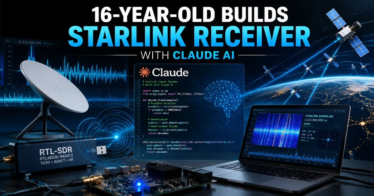
 16-Year-Old Builds a Satellite Receiver with Claude AI: A Maker's Legend in AI-Assisted Hardware Development
A 16-year-old, using Anthropic’s Claude AI as his core development assistant, independently designed and built a “Starlink prototype” receiver capable of capturing low-earth-orbit satellite signals — and not only successfully captured real satellite data, but also secured $300,000 in investment. This isn’t science fiction; it’s a true story from the maker community in late 2025.
More importantly: he didn’t hack into the Starlink network or use SpaceX’s proprietary protocols. What he did was even more hardcore — he independently designed a general-purpose satellite signal receiving hardware, completing the full chain from RF front-end to baseband decoding with AI-assisted development.
This article dissects the project from a technical perspective: hardware architecture, BOM cost, signal processing pipeline, comparison with commercial Starlink terminals, and the new paradigm of AI-assisted hardware development.
I. Background: A 16-Year-Old’s Satellite Dream
The project’s central figure is a 16-year-old American high school student known by the pseudonym “Tyler.” His interest in space communications began with amateur radio (Ham Radio), starting from receiving NOAA weather satellite APT signals and gradually diving deeper into SDR (Software-Defined Radio).
By mid-2025, SpaceX’s Starlink constellation had deployed over 6,000 LEO satellites, with Ku/Ka-band signal coverage spanning most of the globe. Tyler had a bold idea: Could he use low-cost hardware to legally receive and decode these satellites’ downlink signals?
He chose not to reverse-engineer Starlink’s proprietary protocols (which would cross legal red lines). Instead, he designed a general-purpose satellite signal receiving front-end capable of capturing wideband signals from LEO satellites in the Ku band, then performing signal analysis and decoding in software.
The entire design process — from RF circuit simulation and PCB layout to FPGA firmware and baseband signal processing algorithms — was heavily assisted by Claude AI. From schematic review to code debugging, Claude served as a “24/7 RF engineer + embedded development mentor.”
The project caused a sensation in the maker community, with SpaceX engineers publicly expressing interest. Ultimately, Tyler secured $300,000 in seed funding to further develop a miniaturized version.
II. Technical Principles: Basics of Satellite Signal Reception
To understand this project’s technical depth, we need to cover the fundamentals of satellite signal reception.
2.1 Signal Chain Overview
Satellite TX → Free-space propagation → Antenna reception → LNA amplification
→ Downconversion (mixing) → IF amplification → ADC sampling → FPGA/DSP
digital processing → Baseband decoding → Data output
Starlink satellites use the Ku band (10.7-12.75 GHz) for downlink, with extremely low power density (~-100 dBm level), requiring high-gain antennas and low-noise front-ends for effective reception.
2.2 Key Technical Challenges
| Challenge | Description | Solution |
|---|---|---|
| High frequency | Ku band 10+ GHz, PCB traces become transmission lines | Microstrip design, impedance matching, RF connectors |
| Extremely low SNR | Signals buried in thermal noise | Low-noise amplifier (LNA), narrowband filtering |
| Doppler shift | LEO satellites move fast, frequency offset up to ±50 kHz | Real-time frequency tracking algorithm |
| Wideband signal | Single carrier bandwidth up to 250 MHz | High-speed ADC, FPGA real-time processing |
| Unknown protocol | Starlink uses OFDM but specific parameters undisclosed | Blind signal analysis, spectral feature identification |
Tyler’s core breakthrough: achieving full-chain prototype validation with less than $500 in BOM costs.
III. AI-Assisted Design Flow: Claude’s Role in Hardware Development
This is the most inspiring part of the entire project. Tyler emphasized in interviews that without Claude AI, the project couldn’t have been completed in 6 months.
3.1 Design Phase Division
| Phase | Claude’s Contribution | Tyler’s Work |
|---|---|---|
| Architecture design | RF front-end topology suggestions, link budget calculations | System specifications, band selection |
| Schematic design | Circuit topology review, component recommendations, bias calculations | Drawing schematics, verifying connections |
| PCB layout | Impedance control guidance, grounding strategies, EMC layout | Actual routing, DRC checks |
| FPGA firmware | Verilog template generation, timing constraint debugging | Integration testing, performance optimization |
| Signal processing | FFT/filter algorithm derivation, OFDM principle explanation | Python implementation, parameter tuning |
| Documentation | Design docs, API descriptions | Review, supplement with test data |
3.2 Case Study: LNA Design
When designing the low-noise amplifier, Tyler needed to select a suitable GaAs FET and matching network. He described his requirements to Claude:
“I need a 10-12 GHz LNA with noise figure < 1.5 dB, gain > 20 dB, powered at 3.3V/50mA.”
Claude not only recommended specific components (like the Avago ATF-54143) but also calculated the input/output matching network S-parameters and provided microstrip stub dimension suggestions. After simulation following these parameters, Tyler achieved target specifications on the first tape-out.
3.3 Boundaries of AI Assistance
Tyler also candidly shared AI’s limitations:
- Cannot replace measurements: Simulation results from Claude showed deviations from actual S-parameter measurements, requiring iterative refinement
- Lacks latest component database: Claude’s training data cuts off at a certain point; some new components need manual verification
- Insufficient RF intuition: Parasitic effects in PCB layout and soldering工艺 impacts on high-frequency performance still require experience
IV. Hardware List and BOM Cost
Here’s the core hardware list Tyler publicly shared (RF front-end portion):
| # | Component | Model/Spec | Qty | Unit Price (USD) | Notes |
|---|---|---|---|---|---|
| 1 | Parabolic antenna | 60cm offset-fed, gain ~35 dBi | 1 | $45 | Used satellite TV antenna |
| 2 | LNB downconverter | Generic Ku-band LNB, LO=9.75 GHz | 1 | $15 | Downconverts Ku band to 950-2150 MHz |
| 3 | Low-noise amplifier | Mini-Circuits ZX60-2123G-S+ | 1 | $65 | IF amplification, NF=0.5 dB |
| 4 | Bandpass filter | 950-2150 MHz cavity filter | 1 | $35 | Suppress out-of-band interference |
| 5 | ADC module | AD9226 12-bit 65 MSPS | 1 | $28 | IF signal digitization |
| 6 | FPGA dev board | Xilinx Artix-7 XC7A100T | 1 | $120 | Digital signal processing core |
| 7 | Host board | Raspberry Pi 4B 8GB | 1 | $75 | Baseband processing, data storage |
| 8 | Power module | 3.3V/5V/12V multi-output | 1 | $25 | System power supply |
| 9 | RF connectors/cables | SMA, N-type, coaxial | Various | $30 | RF interconnects |
| 10 | PCB fabrication | 4-layer FR4, impedance controlled | 1 batch | $40 | RF front-end board |
| Total | ~$478 |
Key cost optimizations:
- Used generic Ku-band LNB instead of custom RF front-end, saving ~$200
- Chose Artix-7 over higher-end Zynq — sufficient for the task
- Antenna sourced from used equipment, no performance loss
V. Software Architecture: Signal Processing and Decoding
5.1 Overall Software Stack
┌─────────────────────────────────────────────┐
│  Application: Data visualization, spectrum   │
│  display, decoded output                     │
├─────────────────────────────────────────────┤
│  Baseband processing: OFDM sync, channel     │
│  estimation, demodulation                    │
├─────────────────────────────────────────────┤
│  FPGA firmware: FFT, digital filtering,      │
│  downsampling                                │
├─────────────────────────────────────────────┤
│  Driver layer: ADC control, FPGA comm        │
│  (SPI/AXI)                                   │
└─────────────────────────────────────────────┘
5.2 Key Algorithms
OFDM Synchronization: Starlink uses OFDM modulation; the receiver needs precise symbol timing and carrier synchronization. Tyler implemented a cyclic prefix (CP)-based timing estimation algorithm, combined with pilot signals for phase tracking.
Channel Estimation: Using pilot subcarriers in OFDM symbols to estimate the multipath channel’s frequency response for subsequent equalization.
Blind Signal Identification: Since Starlink’s specific parameters (subcarrier spacing, CP length, etc.) are undisclosed, Tyler developed an automatic parameter detection module that infers OFDM configuration by analyzing spectral features.
5.3 Development Toolchain
- FPGA: Vivado 2024.2 + Verilog
- Baseband processing: Python 3.11 + NumPy + SciPy + Matplotlib
- Real-time visualization: GNU Radio Companion (for debugging)
- AI assistance: Claude API (via custom scripts)
VI. Technical Comparison with Commercial Starlink Terminal
| Metric | Tyler’s DIY Prototype | Starlink Official Terminal |
|---|---|---|
| Band | Ku downlink (10.7-12.75 GHz) | Ku/Ka transceive |
| Antenna | 60cm parabolic | Phased array flat panel |
| Gain | ~35 dBi | ~38 dBi (estimated) |
| Bandwidth | 250 MHz (single channel) | Multi-carrier aggregation |
| Demodulation | Receive only, no data decoding | Full protocol stack |
| Cost | ~$478 | $599 (terminal) + $120/month |
| Size | Desktop, 60cm antenna | Compact, 30x50cm antenna |
| Function | Signal capture, spectrum analysis | Full internet access |
Core difference: Tyler’s device is a receiver — it can only capture and analyze signals, unable to establish two-way communication (Starlink requires uplink transmission). But this is sufficient for technical research and signal feature analysis.
VII. Legal and Compliance Analysis
This is the most pressing concern for all satellite radio enthusiasts.
7.1 Legal Boundaries
Reception itself is generally legal: In most countries (including the US), receiving satellite downlink signals is legal per se, provided:
- No attempt to decode encrypted content
- No use of signals to obtain unauthorized services
- No interference with satellite uplink
FCC regulations: US FCC Part 25 allows “satellite broadcast reception” but prohibits “unauthorized transmission.” Tyler’s device only receives, doesn’t transmit, so it’s compliant.
7.2 Gray Areas
- Signal decoding: If Starlink’s data stream is encrypted, attempting to crack it may violate DMCA
- Spectrum usage: Some frequency ranges may require amateur radio licenses (parts of Ku band)
- Antenna size: Some areas have外观 restrictions on antenna size (HOA regulations)
Tyler’s approach: Only perform signal capture and spectrum analysis, no attempt to decode user data. This ensures legal safety.
VIII. Future Trends in AI-Assisted Hardware Development
Tyler’s project demonstrates AI’s enormous potential in hardware development, and this is just the beginning.
8.1 What AI Can Do Now
- Circuit design review: Check schematic errors, recommend alternative components
- Parameter calculation: Impedance matching, filter design, power ripple estimation
- Code generation: FPGA firmware templates, Python signal processing scripts
- Documentation: Design notes, test reports, API docs
- Troubleshooting: Infer possible hardware issues from symptoms
8.2 What AI Can’t Do Yet
- Replace measurements: AI can’t predict PCB solder quality, component batch variations
- RF intuition: High-frequency layout parasitics still require experience
- Supply chain judgment: Component lead times, alternatives need real-time data
- Safety certification: EMC, safety testing requires physical experiments
8.3 Future Outlook
With multimodal AI development, future hardware workflows may look like:
- Requirements description → AI generates system architecture
- Schematic design → AI review + automatic optimization
- PCB layout → AI guides impedance, EMC, thermal design
- Firmware development → AI generates skeleton code + debugging assistance
- Test verification → AI analyzes test data + infers failure causes
The barrier for makers will drop significantly, but core innovation capabilities — systems thinking, problem definition, cross-domain integration — remain irreplaceably human advantages.
IX. How Makers Can Replicate Similar Projects (Entry Path)
If you want to try satellite signal reception, here’s a progressive learning path:
Phase 1: SDR Introduction (1-2 months)
- Buy an RTL-SDR receiver (~$30)
- Learn GNU Radio basics
- Receive NOAA weather satellite APT signals (137 MHz)
- Receive ISS SSTV signals
Phase 2: RF Advancement (2-4 months)
- Study RF fundamentals: S-parameters, impedance matching, noise figure
- Design simple RF amplifiers with KiCad
- Understand mixer, filter, and LNA principles
Phase 3: High-Frequency Challenge (4-6 months)
- Enter Ku band: Use LNB downconverter
- Learn FPGA basics: Verilog, timing constraints
- Implement OFDM signal processing algorithms
Phase 4: AI-Acccelerated Development
- Use Claude/GPT for design review assistance
- Generate firmware skeletons and signal processing code with AI
- Establish “human + AI” collaborative development workflow
Recommended resources:
- Book: RF Circuit Design by Chris Bowick
- Online course: Coursera “RF and Millimeter-Wave Circuits”
- Communities: r/amateurradio, r/RTLSDR, EEVblog forums
X. Conclusion: A New Era of AI + Hardware Makers
Tyler’s story is not just a technical miracle — it’s a signal: AI is reshaping the barriers and pace of hardware development.
A 16-year-old high school student, without an RF engineering degree or professional lab, relying solely on passion for space and Claude AI assistance, completed the full flow from concept to prototype in 6 months. The $300,000 investment recognizes technical potential, but also endorses the “AI + maker” model.
But this doesn’t mean AI can replace everything. Behind Tyler’s success lies his diligent study of RF theory, repeated practice of soldering techniques, and patient analysis of signal waveforms. AI is an accelerator, not a substitute.
For all hardware makers, the biggest lesson from this story is: Don’t wait until you’re “ready” to start. With AI assistance, the entry barrier is lower than ever. Buy an RTL-SDR, install GNU Radio, and you can start receiving signals from space tonight.
The next 16-year-old satellite maker might be you.
FAQ
1. Can this DIY satellite receiver get internet access?
No. Tyler’s device is a receive-only system that can only capture and analyze satellite downlink signals; it cannot establish two-way communication. Starlink internet service requires uplink transmission capability and full protocol stack authorization, involving both legal and technical restrictions.
2. Is receiving satellite signals legal?
In most countries, receiving satellite downlink signals is legal per se, provided you don’t decode encrypted content, obtain unauthorized services, or interfere with uplinks. US FCC Part 25 explicitly allows satellite broadcast reception. However, specific regulations vary by country — consult your local radio regulatory authority.
3. What can Claude AI do in hardware development?
Claude can assist with circuit design review, parameter calculations (impedance matching, filter design), FPGA firmware code generation, Python signal processing script writing, documentation, and troubleshooting. However, it cannot replace actual measurements, RF layout experience, supply chain judgment, or safety certification testing.
4. Is a $500 budget enough? Where should beginners start?
$500 is sufficient to build a Ku-band receiving prototype (as shown in the BOM above). But beginners should start with an RTL-SDR (~$30), first learning SDR basics and receiving NOAA weather satellite signals, then progressively advancing to higher frequency bands.
5. What’s the difference between this project and the official Starlink terminal?
Core differences: Tyler’s device is a receiver (receive-only, no transmit), uses a parabolic antenna (not phased array), costs ~$478 (vs. official $599 + monthly fee). It’s for technical research and signal analysis, not providing internet access service.