 Embedded Development
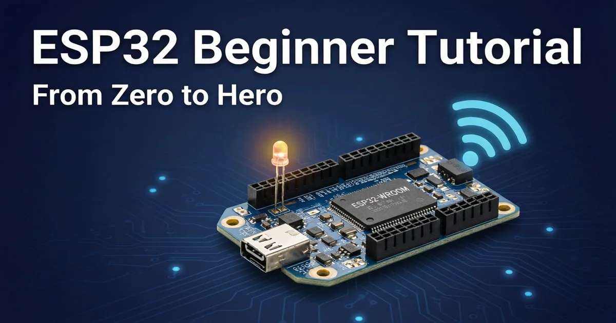
 ESP32 Beginner Tutorial 2026 | Pinout + First LED Blink + Wi-Fi Setup
Searching for “eps32”? You probably mean ESP32 — Espressif Systems’ dual-core Wi-Fi + Bluetooth microcontroller. This tiny chip has become the go-to platform for IoT developers and electronics hobbyies for good reason: it’s affordable ($3-6 per board), powerful (dual-core 240MHz), and comes with built-in Wi-Fi and Bluetooth.
This tutorial takes you from zero to your first working ESP32 project. Even if you’ve never touched embedded development, you’ll have an LED blinking within 30 minutes.
Why Choose ESP32?
After the ESP8266, Espressif launched the ESP32 with major upgrades:
| Feature | ESP8266 | ESP32 | ESP32-S3 |
|---|---|---|---|
| CPU | Single-core 80MHz | Dual-core 240MHz | Dual-core 240MHz |
| Wi-Fi | 802.11 b/g/n | 802.11 b/g/n | 802.11 b/g/n |
| Bluetooth | None | BT 4.2 + BLE | BT 5.0 + BLE |
| GPIO | 17 | 34 | 45 |
| Flash | External | 4-16MB | 8-16MB |
| PSRAM | None | 4MB | 8MB |
Typical ESP32 use cases:
- Smart home devices (pair with Matter protocol)
- Sensor data collection and cloud upload
- Wireless remote controls and IoT gateways
- SDR software-defined radio DIY projects
- Battery-powered low-power devices
What You Need
Hardware List
| Item | Qty | Price | Notes |
|---|---|---|---|
| ESP32 dev board | 1 | $3-6 | ESP32-DevKitC or ESP32-WROOM-32 recommended |
| Micro-USB data cable | 1 | $1-2 | Must be a data cable, NOT a charge-only cable |
| LED | 1 | $0.02 | Any color |
| 220Ω resistor | 1 | $0.01 | Current limiting for LED |
| Breadboard | 1 | $2-4 | Standard 830-hole breadboard |
| Jumper wires | Several | $2 | Male-to-male, male-to-female |
Critical note: Many beginners buy the wrong cable — you MUST get a Micro-USB data cable, not a charge-only cable. Charge-only cables lack the data lines and won’t be detected by your computer.
Software Setup
-
Download Arduino IDE 2.x: https://www.arduino.cc/en/software
-
Add ESP32 board support:
- Open Arduino IDE → File → Preferences
- In “Additional Board Manager URLs” add:
https://raw.githubusercontent.com/espressif/arduino-esp32/gh-pages/package_esp32_index.json- Tools → Board → Board Manager → Search “esp32” → Install
-
Install USB driver (depending on your board’s chip):
- CP2102: Download from Silicon Labs website
- CH340: Download from WCH website (common on budget boards)
Understanding the ESP32 Board
Using the popular ESP32-DevKitC V4 as example:
        ┌─────────────────────┐
        │      ESP32          │
        │   ┌───────────┐     │
 USB ───┤   │  ESP-WROOM │     ├─── 3V3  EN  VP  VN  D34-D39
        │   │   -32      │     │
        │   └───────────┘     ├─── GND  D2  D4  RX2  TX2
        │                     │
        └─────────────────────┘
Key Pin Functions
| Pin | Function | Notes |
|---|---|---|
| 3V3 | 3.3V power output | Max 500mA |
| GND | Ground | Multiple GND pins available |
| GPIO2 | Onboard LED | Many boards have a built-in blue LED |
| GPIO0 | Boot mode select | Must be pulled LOW for firmware upload |
| EN | Reset/Enable | Pull LOW to reset the chip |
| TX0/RX0 | Serial communication | Connected to USB-to-serial chip |
| TX2/RX2 | Second UART | For communication with other devices |
Tip: Pin layouts vary between manufacturers. Always check the datasheet or search for your board model + “pinout” before wiring.
First Project: Blink an LED
This is the embedded world’s “Hello World” — make an LED blink at 1-second intervals.
Wiring Diagram
ESP32 GPIO2 ──── 220Ω Resistor ──── LED Anode (long leg)
                                      │
                                      LED Cathode (short leg)
                                      │
ESP32 GND ────────────────────────────┘
Wiring steps:
- Insert ESP32 into the breadboard
- Connect GPIO2 to one end of the resistor via jumper wire
- Connect the other resistor end to the LED anode (long leg)
- Connect the LED cathode (short leg) to ESP32 GND
Write the Code
Open Arduino IDE and enter this code:
// ESP32 LED Blink Example
#define LED_PIN 2  // GPIO2, most boards have a built-in blue LED

void setup() {
  // Initialize LED pin as output
  pinMode(LED_PIN, OUTPUT);

  // Initialize serial communication (for debugging)
  Serial.begin(115200);
  Serial.println("ESP32 LED Blink program started");
}

void loop() {
  digitalWrite(LED_PIN, HIGH);  // Turn LED ON
  Serial.println("LED ON");
  delay(1000);                  // Wait 1 second

  digitalWrite(LED_PIN, LOW);   // Turn LED OFF
  Serial.println("LED OFF");
  delay(1000);                  // Wait 1 second
}
Upload the Firmware
- Select board: Tools → Board → ESP32 Arduino → “ESP32 Dev Module”
- Select port: Tools → Port → Choose your COM port (Windows) or /dev/ttyUSB0 (Linux) / /dev/cu.usbserial-* (macOS)
- Click the Upload button (→ arrow)
Common issues:
- “Failed to connect to ESP32”: Hold the BOOT button (GPIO0) on the board, then click Upload. Release BOOT after you see “Connecting…”
- “COM port not found”: Verify your USB cable is a data cable and the driver is installed correctly
Next Step: Connect to Wi-Fi
One of ESP32’s most powerful features is built-in Wi-Fi. Here’s a sketch that connects to Wi-Fi and prints the IP address via serial:
#include <WiFi.h>

const char* ssid = "YourWiFiName";
const char* password = "YourWiFiPassword";

void setup() {
  Serial.begin(115200);
  delay(1000);

  Serial.println();
  Serial.print("Connecting to Wi-Fi: ");
  Serial.println(ssid);

  WiFi.begin(ssid, password);

  // Wait for connection
  while (WiFi.status() != WL_CONNECTED) {
    delay(500);
    Serial.print(".");
  }

  Serial.println();
  Serial.println("Wi-Fi connected!");
  Serial.print("IP address: ");
  Serial.println(WiFi.localIP());
  Serial.print("Signal strength: ");
  Serial.print(WiFi.RSSI());
  Serial.println(" dBm");
}

void loop() {
  // Add your main logic here
  delay(1000);
}
After uploading, open the Serial Monitor (Tools → Serial Monitor, baud rate 115200). You’ll see:
Connecting to Wi-Fi: YourWiFiName
.....
Wi-Fi connected!
IP address: 192.168.1.100
Signal strength: -45 dBm
What’s Next: Explore More ESP32 Features
After completing this tutorial, continue learning:
- ESP32 Advanced Features: EEPROM storage, UART serial communication, OTA wireless updates
- ESP32-C6 Matter Smart Home: Build a Matter-protocol smart home with ESP32-C6
- ESP32-S3 SDR DIY: Build a full-band software-defined radio with ESP32-S3
- ESP32 Real-time AI SDK: Run speech recognition and image classification on ESP32
FAQ
Q: Is “eps32” the same as ESP32?
A: Yes — “eps32” is a common misspelling of ESP32. Google auto-corrects the spelling, so searching “eps32” will show ESP32 results. This tutorial includes the misspelling to help users who type it wrong find the right content.
Q: What’s the difference between ESP32 and Arduino?
A: Arduino is a development platform and programming language (based on C++), while ESP32 is a hardware chip. You can program ESP32 using the Arduino IDE, or use ESP-IDF (Espressif’s official SDK) for native development. ESP32 is significantly more powerful (dual-core 240MHz vs Arduino’s 16MHz) and has built-in Wi-Fi and Bluetooth.
Q: Can ESP32 drive 5V devices directly?
A: No. ESP32 GPIO operates at 3.3V logic levels. Connecting 5V devices directly may damage the chip. Use a level shifter (like TXS0108E) or voltage divider resistors to convert 5V signals to 3.3V.
Q: Why does my ESP32 keep restarting?
A: Common causes:
- Insufficient power: Poor-quality USB cable or USB port can’t supply enough current. Try a better cable.
- Code issues: Watchdog timeout — check for infinite loops or blocking operations.
- Memory overflow: PSRAM not properly initialized, or large arrays causing stack overflow.